Using CutWorks
This section introduces several important topics that should be reviewed before using the CutWorks Software including:
-
Overall summary of the software
-
Different aspects of the screen or desktop
-
Workflow for using the software
-
Introduction to the user guide
-
Instructions for starting the software
-
Description of several important parameters that should be set before starting to use the software
1.1 About the Software
The CutWorks Software described in this manual consists of several modules for working directly with cut job files:
-
Base Module. Use the Base Module (or right-click for Select Mode) to open job files and to perform a variety of job processing functions before cutting. Refer to Chapters 2, 3, and 4 for more information on using the Base Module.
-
Nesting modules. Use the optional nesting modules to move parts around the material to obtain a better fabric yield. The list of nesting modules: Manual Nest, AutoNest Plain, AutoNest Pro, ComposiNest, AutoNest Match, and AutoNest Leather. The modules you use depend on how nesting is done at your facility. Refer to Chapter 5 for more information on using the nesting modules.
-
SimulNest Module. Use the optional SimulNest Module to run a second AutoNest computer. Refer to the CutWorks Software System Administration Guide for more information on this module.
-
Matching modules. Use the optional matching modules to match parts to the fabric or to other parts. The matching module, Projector Match, is primarily used on the DCS 3500/3600 cutting machines. See the Getting Started for the DCS 3500/3600 cutter for information about the Matching Module.
-
ToolPath Module. Use the optional ToolPath Module to improve how the job will be cut, saving time and wear on the cutting machine. Refer to Chapter 6 for more information on using the ToolPath Module.
-
Administrator Module. This module is required to use Computer Integrated Manufacturing (CIM). This module is a license agreement that allows many computers installed and on a network (called clients) to access one database. Refer to the CutWorks Software System Administration Guide for information on using the Administrator Module.
-
Client Module. This module provides access to a database that is used to organize and process cut jobs. This module uses work orders to organize information which is stored in the database on a network. You can access the information in the database to create detailed reports about material usage, yields, cutting time, and other important information relating to production. This module is required with Taurus cutters. Refer to the CutWorks Software System Administration Guide for information on using the Client Module.
-
Vision Module. Use the Vision Module to scan leather hides, locate markings on hides, perform camera calibrations, and other tasks that require a camera. The Vision module is available only for machines with a camera installed.
-
CADLink Module. Use the optional CADLink Module to create, digitize, and edit parts using a program based on AutoCAD. This allows for seamless transfer of new or edited parts between the CADLink Module and Base Module.
1.2 About this User Guide
Only those tasks—typically file preparation tasks—that can be performed using the CutWorks Software without a cutting machine attached, are discussed in this manual. After files have been prepared using the CutWorks Software, refer to Getting Started for your cutting machine to run the job on the cutting machine.
This manual describes the following concepts:
-
Chapter 1, Using Cutworks describes how to install the CutWorks Software, and provides information about the USB device and license needed to run the software. This chapter also provides detailed information about the CutWorks interface, how to set interface preferences, and how to use the CutWorks Software Online Help. This chapter also explains the conventions used in the manual and in the software.
-
Chapter 2, Working with Jobs describes how to open and process standard cut files that have been developed on a wide range of design and nesting systems. This chapter provides the user with detailed information on how to use the software to open job files, create new job files, save and close job files, and print job files. This chapter also provides detailed information on the File Wizard to automate tasks.
-
Chapter 3, Changing the View describes how to use the various CutWorks Software commands to change how the parts are displayed in the software. The view commands are used to: zoom in or out; display the parts based on part counts, part placement, or other factors; add arrows to indicate cut path; and show the borders of the material.
-
Chapter 4, Editing a Job describes how to edit and modify job files for use on GERBERcutters, as well as machines from other manufacturers.
-
Chapter 5, Nesting a Job discusses how to use the optional nesting modules to create nests or markers both manually and automatically. This chapter provides the user with detailed information on how to: create a fabric repeat grid; automatically expand or contract the fabric repeat grid; how to manually move parts around in a marker; and how to automatically nest parts or blocks of parts.
-
Chapter 6, ToolPathing a Job describes how to use the optional ToolPath Module to optimize cutting by stringing polylines together and by changing the order of a job.
-
Chapter 7, Using the Database discusses how to use the optional database to help manage the cutting operation at your facility.
-
The Glossary defines terms that are unique to the CutWorks Software and cutting systems.
-
There is an Index to assist in locating information.
1.2.1 Manual Conventions
The manual uses the following conventions:
-
Commands and Toolbar Buttons. When describing commands that are listed on a menu, the command name is bold. This convention is used in procedures/how-tos.
Example: To open the Auto-Map Arcs dialog box, click the Auto-Map Arcs button (or click Edit menu, select Edit Geometry, then click the Auto-Map Arcs command). -
Instructions. When describing how to perform a task, the toolbar button associated with the task is included.
 Example: To access a shortcut menu, click the desktop with the right mouse button.
 -
Clicking an Item. To click an item, press the left mouse button.
-
Right-click an item. To right-click an item, press the right mouse button.
-
Dragging an item. To drag an item, press and hold the left mouse button while moving the mouse in the specified direction.
-
OK and Cancel buttons. Most dialog boxes contain an OK and a Cancel button. If the user clicks the OK button, the software will accept any changes made in the dialog box. If the user clicks the Cancel button, no changes are made and the dialog box closes.
-
Figures. Images that explain concepts, work flow, or show on-screen examples have a Figure X-X caption above the image and are numbered independently of screens. See example of Figure 1-1 on page 24.
-
Dialog Box Screens and Tables. Whenever possible, an example of the dialog box is provided. Most dialog boxes are followed by a table that explains the fields and/or options available in the dialog box. The table is formatted as follows: If the dialog boxes contain functions that are grouped together, the group name is in italics and any fields or options within the group are indented. Also, a dotted table line is added before and after the group. For instance, the example provided below contains a Map to Layer group (italics) which contains the Layer Name field (indented).
Example shown below is a dialog box with screen caption below the image and followed by its table. Screens are numbered independently of figures.
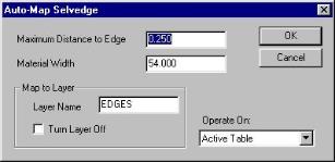
Screen X.X Auto-Map Selvedge Dialog Box
The following options are available in the Auto-Map Selvedge dialog box:
|
Field/Option |
Usage |
|
Maximum Distance to Edge |
The maximum distance... |
|
Material Width |
The actual width... |
|
Map to Layer |
This section includes… |
|
Layer Name |
Type the new |
|
Turn Layer Off |
Select this option |
|
Operate On |
Select an option... |
1.3 Installing the Software
The CutWorks Software must be installed on the computer’s hard disk and a USB device and license is needed on the personal computer to operate the software. Each working copy of the CutWorks Software requires its own USB device.
Installation instructions, PC requirements and information about the USB device are available in the readme.rtf file on the CutWorks Software installation CD. Refer to the CutWorks Software System Administration Guide for more information.
1.4 Starting the Software
 To start the CutWorks Software, double-click the CutWorks Software icon on the Windows desktop. The software starts and the CutWorks Desktop appears. If your system is installed with the optional database, the desktop does not appear. Instead, a user log on dialog box opens. See the next paragraph for more information on logging into the software.
1.4.1 Logging On to the Software for the First Time
If your system has the optional database installed, you must log on to the software each time you open the software. The first time the CutWorks Software is opened, you must use one of the following default user names.
-
Admin. This user name has access to all the functions in the CutWorks Software including those for editing and cutting files. One user should be assigned as the Administrator. This user will add other users, define groups, and assign access to each user and group.
-
Guest. This user name is allowed only to open files and change some view settings. When the software is opened, the User Log On dialog box, shown in Screen 1-1, appears.
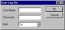
Screen 1‑1 User Log On Dialog Box
The User Log On dialog box contains the following:
|
Field/Option |
Usage |
|
User Name |
Type your user name. |
|
Password |
Type your password. If this box is unavailable (grayed-out), refer to the CutWorks Software System Administration Guide for important information on the Restrict User Access based on User Group option in the CheckPoint Administration dialog box. |
|
Shift |
This field lists the work shifts at your factory. |
When logging on to the software, it is important to specify the correct shift, as this information is used by the database to track system use.
Once you have logged on to the software the first time, you can set up other user names and passwords. Refer to the CutWorks Software System Administration Guide for more information.
1.4.2 Logging Off the Software
Depending on your company’s policies, you may be required to log off the software at the end of your shift, when you go on break, when you finish a particular job, or at any other time.
 To log off the software, click the CheckPoint menu, then select the Log Off command to display the User Log Off dialog box, shown in Screen 1-2. Click OK to log off the software.

Screen 1‑2 User Log Off Dialog Box
Once you log off, your user name is no longer tracked in the database.
After logging off, the User Log In dialog box appears for the next user to log in. A user must log in to continue using the software.
1.5 Screen Orientation
The CutWorks Software main window, or desktop, appears when the job is first started (see Figure 1-1). The desktop features the menu bar, customizable toolbars, windows for master parts and placed parts and a status bar.
Figure 1‑1 Screen Orientation (With Open Job File)
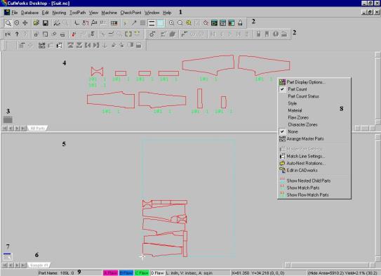
The following are depicted in Figure 1-1:
|
Item |
Name |
Description |
|---|---|---|
|
1 |
Menu Bar |
Lists the different menus within the CutWorks Software. |
|
2 |
Toolbars |
Displays shortcut buttons for the functions of the software. See paragraph 1.5.1. |
|
3, 7 |
Inactive/Active Window Indicator |
A small square icon that appears in the Master Parts Window or Marker Window. The indicator appears with a gray fill when the window is inactive. The indicator appears transparent when the window is active. Click on a window to make that window active. |
|
4 |
Master Parts Window |
Displays a copy of each part in the file. See paragraph 1.5.2. |
|
5 |
Marker Window or Placed Parts Window |
Contains the active job file. See paragraph 1.5.3. |
|
6 |
Table Selection Tab |
Allows you to move from one Marker Window (or Master Parts Window) to another within the same job file. See paragraph 1.5.4. |
|
8 |
Shortcut Menu |
A menu that is displayed when you right-click. The menu contains often used commands. See paragraph 1.5.5. |
|
9 |
Status Bar |
Displays information about the software and the current job file. See paragraph 1.5.6. |
1.5.1 Toolbars
The desktop includes several toolbars, which you may choose to display or not display. You can create new toolbars, and add or remove command buttons from many of the toolbars. Refer to Chapter 3 for more information on the toolbars.
1.5.2 Master Parts Window
The Master Parts Window displays a copy of each part in the file. The user can display the Master Parts in one of the following ways.
-
Splitter Window. The splitter window splits the screen so that the master parts are displayed in a window at the top (horizontally) or right (vertically) of the Marker Window. This is the default view for Master Parts in the nesting modules.
To control the size of the splitter window, move the bar that forms the bottom of the window up or down. -
Child Window. The child window displays the master parts in a separate window within the Marker Window. To move the child window, click the title bar with the mouse and drag the window to the desired location in the Marker Window.
To change the size of the child window, position the cursor on the edge or a corner of the window. The cursor will change to a double-headed arrow. Click with the mouse and drag the edge or corner of the window in or out to change the size.
Use the Preferences dialog box to select the splitter window or child window. Refer to paragraph 1.9.1.
1.5.3 Marker (Placed Parts) Window
The Marker (Placed Parts) Window contains the active job file.
To change the size of the Marker window, position the cursor on the bar between the Marker window and the Master Parts window. When the cursor turns into a double headed arrow, click the left mouse button and drag it down.
1.5.4 Selection Tabs
Your job can have multiple Marker Windows or Master Parts Windows. These extra windows (called tables or tabs) have tabs that allow you to move from one window to another.
1.5.4.1 Master Part Window Tabs
The tabs that appear in the Master Parts Window indicate the material assigned to the master parts, or the part count status of the master parts. The part count status indicates whether the correct number of a part has been placed in the Marker Window. Refer to Chapter 5 for a discussion on the Master Part Window display options.
1.5.4.2 Marker Window Tabs
The tabs that appear in the Marker Window (Table Selection Tabs) display the number of the table, as the tables were added. If the tables have a material assigned, the name of the material appears on the tab. Refer to Chapter 4 for more information on tables, assigning material, and table selection tabs.
1.5.5 Shortcut Menus
The CutWorks Software has a number of shortcut menus that can be used to access commands that are used often. The shortcut menus can operate on the selected parts or all parts as determined by the nature of the command.
For example, while in Select Mode, if you right-click in the Placed Parts Window, the Move to Layer command is available on the shortcut menu after an entity is selected. Or, if you right-click in the Master Parts Window, the Master Part Settings command is available on the shortcut menu after a master part is selected.
To access a shortcut menu, click the desktop with the right mouse button. Right-clicking the Placed Parts window opens a different menu, depending upon the active module. Right-clicking the Master Parts window displays the same menu in all modules.
1.5.6 Status Bar
The status bar that is displayed across the bottom of the screen, is shown in Figure 1-2.
Figure 1‑2 Sample Status Bar

Depending on the selected mode, the status bar will display different information about the software and the current marker. The status bar shown in Figure 1-2 contains the following information:
-
Part Name. When the cursor is placed over a named part, the part name is displayed in the left of the status bar. Use the Master Part Settings dialog box (see Chapter 5) to set the name of the part.
-
Flaw Zones. Four small boxes display flaw zone colors for the job. These boxes appear to the right of the part name any time a hide outline is displayed, or if the Flaw Zones option is selected on the Placed Parts tab in the Part Display Options dialog box. See paragraph 5.4.2 for more information on Part Display Options.
-
Units of measurement. The units of measurement for distance, speed and area appear to the right of the flaw zone colors. Refer to paragraph 1.9.1 to set the preferred units of measurement.
-
X/Y coordinates. The X and Y coordinates for the cursor appear to the right of the units of measurement.
-
Dimension and Yield. On the right of the toolbar, dimension and yield information is displayed.
When the user is in Select or ToolPath Mode, the X and Y coordinates of the lower left and upper right corners of the bounding rectangle around the placed parts is displayed. No yield is displayed in these modes.
If the user switches to Nesting Mode, yield information is displayed. See Chapter 5 for more information on how the yield is calculated and displayed.
1.5.7 Dialog Box Title Bar Buttons
Some of the dialog boxes in the CutWorks Software have buttons in the title bar.
A user can select these buttons to have the software perform a certain function. Refer to Figure 1-3 for a description of each button, and the dialog boxes that contain these buttons.
Figure 1‑3 Title Bar Buttons
|
Title Bar Button |
Function |
Displayed in these |
|
|
Toggles a warning sound on or off. |
Add Material Instance |
|
|
Shows or hides dialog box details. |
Cut Job (Starting Options) |
|
|
Configures a dialog box for bar code scanner input. See paragraph 1.9.7 for more information. |
User Log On |
|
|
Closes a dialog box. |
All dialog boxes |
1.6 Entities, Parts, and Layers
Files that are opened in the software are made up of parts that contain different entities which need to be processed by the software and cutting machine. The entities are usually placed on their own layers so that each can be processed in different ways.
For example, notch entities are normally, but not necessarily, placed on a different layer than drill points so that each type of entity can be cut with a different tool. The notches are cut with a notching tool and the drill points are cut with a punch tool.
Drill points and notch entities can be placed on the same layer. When this happens, the layer name identifies the type of entity included on the layer.
For example, if notch entities, drill points, and polylines are all placed on the CUT layer, there would be three separate CUT layer entries in the Map Layers to Tools dialog box: CUT layer with PLine type, CUT layer with Point type, and CUT layer with Drill type. In this example, you can assign a different tool to each type of entity on the CUT layer. However, if you have two different types of notches to be cut, such as a slit notch and v-notch, each notch type must be on a separate layer.
1.6.1 Entities
Entities are geometric objects that make up parts. Entities are created when a job (also called the marker) is made. The software needs to process each entity in order to complete the job. There are four types of entities: points, polylines, text, and notches. In the CutWorks Software a point can be processed as either a drill or an Operational Stop (Op Stop). The extended toolbar can be set up to display a symbol for each entity in the job as you work with the file. Refer to Chapter 3 for more information on how to customize toolbars.
1.6.2 Parts
A part is a group or collection of entities. For example, Figure 1-4 is a part that was made by grouping polyline and notch entities:
Figure 1‑4 Sample Part and Entities
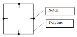
Although the entities will often be already grouped into parts when the job file is opened, the software has two commands, Group into Part and Auto-Group into Parts, which will group the entities for you. These commands are discussed in Chapter 4.
1.6.3 Layers
A layer is a grouping of entities that should all be processed in the same manner such as cut by the same tool, or cut at the same speed. Unlike a part, a layer is not an object that is cut. A layer helps to organize how the whole job is cut.
A layer can be turned off so that the entities are not processed at all. For example, a layer that includes all the text in a marker can be turned off so that the job is cut but not labeled.
A part can include entities that are placed on different layers. In Figure 1-4, the notch entities would normally be on one layer that will be cut with a notching tool, and the polylines in the part would be on another layer that might be cut with a knife or wheel blade.
The CutWorks Software displays layers in different colors. Use the Layer Settings command to create default layers, change the color of the layers, turn layers on or off, and assign points as drills or Op Stops.
Refer to paragraph 4.1 for more information on layers.
1.7 About Materials
Material is a general term to describe anything being cut on one of the cutting machines. For most uses, material is either a fabric roll or sheet, or a leather hide.
The CutWorks Software considers the material used in the job when performing a number of tasks, such as: during matching; when nesting; when determining yield; and when assigning tools.
Matching. When matching, you define where the match points are on the material, and the software places parts according to these match points.
Nesting. When nesting, you enter the width and length of the fabric, or the outline of the leather hide; the software helps to ensure that parts are placed within those parameters.
Yield calculation. When nesting, the yield calculation will be more accurate if based on the dimensions of the material and on the material you are using.
Tool assignment. Each material can have different tools assigned to it, and each tool can have different parameters set for that material. You can use tools that work best with that material, and set each tool to the optimum setting. Users can cut the job without needing to know the specific settings.
The software can use the material parameters to display a representation of the material on screen, to display the parts in the job based on the material they should be cut on, and display a scanned image of the material.
When working with the CutWorks Software, you should be aware of the type of material you are working with, as some commands are specific to each type of material used. This user guide notes if a command works, for example, with a leather hide but not a fabric sheet.
The following terms are used when discussing fabric and leather hides:
|
Term Usage |
Character |
|
Character |
Character is a distinctive physical property of a material, such as thickness, texture, or stretchability. This term is generally used with leather hides to refer to the regions on a hide that are of differing nature. The software allows you to define four different character types to determine where on the material the parts can be placed. See Regions. |
|
Flaw |
A flaw is a defect in the material, such as a scratch or a hole. This term is generally used with leather hides. The software allows you to create up to four types of flaws that are used to determine where on the material parts can be placed. |
|
Regions |
A region is a specific area on a material (usually a leather hide) that can be defined by a common characteristic. The software allows you to define four regions on the material. |
|
Roll |
A roll is any fabric roll. A roll has a specific width, but does not have a specific length. You would use different AutoNest commands on a roll of fabric versus a sheet of material. |
|
Sheet |
A sheet is a piece of fabric with a specific length and width. |
|
Yield |
Yield refers to the percentage of the material covered by the parts in the job. The yield for the marker will change based on whether or not the material is displayed. Refer to paragraph 5.4.3 for more information on yield. |
1.7.1 Displaying Material
The software has several commands that change the appearance of the desktop based on the materials being used in the job.
-
View a material. The Material command on the View menu draws lines on the screen that represent the length and width of the material in the job. When the material is displayed, the software calculates the material yield based on the size of the material. The software also indicates when a nested part is not fully placed on the material. If a part is not fully placed on the material, the part might not cut correctly.
When working with scanned leather hides, the Material command displays an outline of the hide, and indicates any marked flaws on the hide. -
View a scanned image. Taurus leather cutting machines have a camera that scans the hide. The software displays the scanned image on the desktop. When working with scanned leather hides, select the Scanned Image command on the View menu to display an image of the hide you are cutting.
-
Displaying material colors. You can use a set of default colors to help make sure that parts will be cut on the correct material. Use the Part Display Options command to display each part in a color specific to the material that should be used when cutting the part. Refer to Chapter 5 for more information.
1.7.2 Material and Tables
Tables are a convenient way to display parts in the Marker window. Using tables, the parts in a job can be cut multiple times, cut on different material, or as a sub-set of the full marker. A simple way of understanding tables is to think of a table as a single sheet of material, or a single leather hide.
A tab appears at the bottom of the Marker window for each table used in the job. The tab indicates the name of the material assigned to that table, making it easier to place parts on the correct material.
When adding a table to a job that has a leather hide on the active table, the software will use the default settings for a roll of fabric. For more information on using table and materials, refer to paragraph 4.2.
1.7.3 Working with Fabric
When working with fabrics, you must consider the dimensions of the fabric. A fabric has a definite width, and can have a set length that needs to be entered in the software in order to properly place parts for cutting. Use the Material Settings dialog box (see Chapter 5) to enter the dimensions of the fabric into the software.
The fabric dimensions for a specific fabric are different if you are using a sheet of fabric or a full roll of fabric.
-
Sheets. A sheet of fabric has a definite width and length. When nesting onto sheets, you can specify whether to delete parts from the job that do not fit onto the sheet, or to add extra sheets to the job to nest the parts that do not fit. Refer to Chapter 5 for more information on nesting onto sheets.
-
Rolls. A roll of fabric has a definite width. It is not necessary to specify the length.
1.7.4 Working with Leather
The Taurus leather cutting machine is designed for nesting jobs onto, and cutting parts from leather hides. Because each hide is different, the system scans an image of the actual hide and uses the perimeter when nesting and cutting the job.
One of the major differences between leather hides and fabrics is the ability to assign flaw zones on a hide and to scan actual flaws (imperfections) in a hide. You can use flaw zones to dictate which parts can be placed on different areas of the hide. Depending on how your company uses hides, some parts in a leather job can have flaws, while some parts cannot have flaws. The software uses flaws on the hide and flaw zones in the parts to properly place parts on flawed leather.
Flaws are marked on the hide itself, using crayons or colored tape. When the hide is scanned, the software displays the marked flaws on the scanned image. Flaw zones are added to the parts during job development. The flaw zones indicate which flaws the part can be placed on. The CutWorks Software recognizes four types of flaws, usually labeled A through D.
In general, you can place parts with:
-
A flaw zones only on perfect leather or leather marked with A flaw
-
B flaw zones on perfect leather or leather marked with A or B flaws
-
C flaw zones on perfect leather or leather marked with A, B or C flaws
-
D flaw zones on perfect leather or leather marked with any flaw
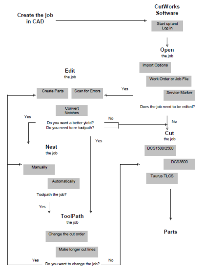
1.8 Workflow
The information in this manual is provided in the order that the job should be processed. Generally, the workflow is similar for all machine types. However, the specific commands for opening, processing, and cutting a job differs depending on the material being cut. For example, you may be cutting fabric on a 1500/2500/3500/3600 series Digital Cutting System (DCS) machine or cutting leather hides on a Taurus cutting machine. Also, the workflow will be different if you have the optional database.
For more information on workflow based on your specific machine type, contact Gerber Technology to schedule machine operator training.
Refer to Figure 1-5 on the next page for a diagram that maps the typical workflow using the CutWorks Software.
Figure 1‑5 Workflow Diagram
1.9 Preferences
Preferences are user settings that control the operation and appearance of the program. These settings are remembered from one session to the next. Once the settings are made, they remain the same each time the CutWorks Software is opened.
To set Preferences, click the Preferences command on the File menu to display the Preferences dialog box, shown in Screen 1-3.
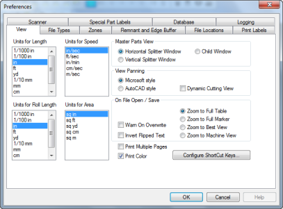
Screen 1‑3 Preferences Dialog Box
The Preferences dialog box is divided into ten tabs. These tabs allow you to set the following:
-
The desktop View, including the units of measure and panning options used when you open a file
-
The File Types used at your facility, and how to display each type
-
How to display files that contain flaw and character Zones, how to add one or more seam allowances to all parts in a file, and how this seam allowance will be displayed
-
How Remnant area and Edge Buffer is displayed on leather hides
-
The File Locations of important files used with the database
-
How labels will be printed when the Print Labels command is used
-
Which COM Port (on the computer) has a bar code Scanner attached
-
How to display files that contain Special Part Labels, including labels used to set nesting priority, define welt, and define orientation constraint
-
How the software opens work orders contained in the Database, and how cut information is recorded in the database.
-
The filter levels for Logging data for specific CutWorks activities.
Refer to the following paragraphs for an explanation of the options contained on each tab in the Preferences dialog box.
1.9.1 View
The View tab in the Preferences dialog box, shown in Screen 1-3, is used to set or change the way the software displays jobs on screen. Once the units for the length and speed are set, the units are used in all relevant dialog boxes as you work with the CutWorks Software.
Define settings and views using the following fields and options on the View tab in the Preferences dialog box:
|
Field/Option |
Usage |
|---|---|
|
Units for Length |
Select the units desired to measure distances. |
|
Units for Roll Length |
Select the units desired to measure roll lengths. |
|
Units for Speed |
Select the units desired to measure speeds. |
|
Units for Area |
Select the units desired to measure area. |
|
Master Parts View |
These options control the type of window that will be used to display Master Parts. Any change made in this group will be displayed the next time a file is opened. |
|
Horizontal Splitter Window |
Splits the screen so that the Master Parts are displayed in a window above the Marker Window. |
|
Vertical Splitter Window |
Splits the screen so that the Master Parts are displayed in a window to the right of the Marker Window. |
|
Child Window |
Displays the Master Parts in a separate window within the Marker Window. |
|
View Panning |
These options determine how the software behaves when using the middle mouse button (rotary wheel) to pan. |
|
Microsoft style |
Uses Microsoft style panning. When you click the middle mouse button, the cursor changes to a gray base point. As you drag the mouse, the window “floats” and moves in the same direction as the mouse. A white arrow appears, indicating the direction of the pan. The further the white arrow is from the circle, the faster the view moves. Rotate the wheel while panning to zoom the view in or out. |
|
AutoCAD style |
Uses AutoCAD style panning. When you click the middle mouse button the cursor changes to a hand. As you drag the mouse, the view moves around in the window at a constant speed. Rotate the wheel while panning to zoom the view in or out. |
|
Dynamic Cutting View |
Select this option to advance the view of the job as it is cutting on a DCS 3500/3600 conveyor cutter. |
|
On File Open/Save |
These options determine how the jobs appear when opened and how files are saved. |
|
Warn on Overwrite |
Select this option to be warned before overwriting an existing file. |
|
Invert Flipped Text |
Select this option to invert any flipped text before saving file. |
|
Print Multiple Pages |
Select this option to print multiple pages. |
|
Print Color |
Select this option to print in color. |
|
Zoom to Full Table |
Displays the entire table as defined in the Configuration and Calibration dialog boxes (See the Getting Started for your machine). |
|
Zoom to Full Marker |
Displays all the pieces of the job. |
|
Zoom to Best View |
Displays the job in either full table or full marker view, depending which is best for the job that is being opened. |
|
Zoom to Machine View |
Displays the job in Machine View. Machine View changes the desktop display to reflect the view from a projector. Machine View is set using the Set Machine View command on the View menu. |
|
Configure Shortcut Keys |
Click this button to customize the keyboard for use with CutWorks Software commands. See paragraph 1.9.1.1 for more information. |
1.9.1.1 Creating Shortcut Keys
A shortcut key is a key or combination of keys on the keyboard that cause the program to perform a specific command. The CutWorks Software has some pre-set shortcuts. These shortcuts are either single-button shortcut keys or drag mode shortcuts.
-
Single-button shortcut keys. These shortcut keys activate assigned commands when one keyboard key is pressed. For example, press the L key on your keyboard to open the Layer Settings dialog box. These shortcuts can be changed.
-
Drag mode shortcuts. These shortcut keys activate the assigned command when one keyboard key is pressed while the user clicks and drags a part. Note that you must have one of the optional nesting modules licensed to the USB device on the computer in order to move parts. These shortcuts cannot be changed.
Press F1 for Help (or click the Help menu, then selecting the Contents command) to search for a list of existing shortcut keys.
To set up or change shortcut keys, click the File menu, then Preferences to display the Preferences dialog box. In the Preferences dialog box, click the Configure Shortcut Keys button located on the View tab to display the Shortcut Keys dialog box shown in Screen 1-4.
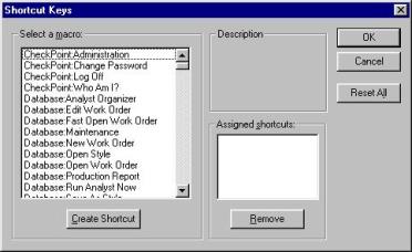
Screen 1‑4 Shortcut Keys Dialog Box
Set shortcuts using the following fields and options in the Shortcut Keys dialog box:
|
Field/Option |
Usage |
|
|
|
|
Select a macro |
This list contains all of the menu commands that can have a shortcut assigned. Click on a command to select it. |
|
Create Shortcut |
Click this button to create a shortcut for the selected command. |
|
Description |
This section describes the function of the selected command. |
|
Assigned shortcuts |
This box lists all of the shortcuts that have been created for the selected command. |
|
Remove |
Click this button to delete the selected shortcut from the Assigned shortcuts list. |
|
Click this button to remove all customized shortcuts and restore the CutWorks Software default shortcuts. |
To create a shortcut:
-
Click the File menu, then Preferences to display the Preferences dialog box.
-
In the Preferences dialog box, click the View tab. Click the Configure Shortcut Keys button to open the Shortcut Keys dialog box.
-
In the Shortcut Keys dialog box, select a command in the Select a macro list and click the Create Shortcut button. The Assign Shortcut dialog is displayed.
-
Press the keyboard keys that you want to use as the shortcut for the selected command. Use any combination of Ctrl, Alt, Shift and/or any keyboard key. The Assign Shortcut dialog box will display the combination that you type, and will indicate if the shortcut is currently assigned to another command.
-
Click OK to accept the shortcut key combination, or click Cancel to exit the dialog box without making changes.
1.9.2 File Types
The File Types tab in the Preferences dialog box, shown in Screen 1-5 is used to set the type of files (or format) that the CutWorks Software can use. By doing this, you control or limit the file types that are displayed in the Open, Save As, and File Wizard Directory dialog boxes. The CEI and DXF file types are always available because the program needs these file types in order to function properly. The CEI and DXF file types cannot be removed.
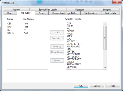
Screen 1‑5 Preferences Dialog Box: File Types Tab
The File Types tab contains the following fields and options:
|
Field/Option |
Usage |
|---|---|
|
Format |
This box lists the format types that the software will recognize. |
|
File Names |
The file extension of the Format. |
|
Available Formats |
This box lists the available format types that can be added to the Format list box. |
|
Add |
Click this button to add a highlighted Available Formats to the Format list box. |
|
Remove |
Click this button to remove a highlighted format from the Format list box. If you attempt to remove the CEI or DXF format, a message box will be displayed to alert you that the program needs these file types in order to function properly. |
|
Move Up |
Click this button to move a highlighted format in the Format list box up one position in the queue. |
|
Move Down |
Click this button to move a highlighted format in the Formats list box down one position in the queue. |
|
Options |
Click this button to display the import options dialog box for the file format highlighted in the Format list box. Not all file types have import options. |
To add a file type to the Format list box:
-
Click the File menu, then Preferences to display the Preferences dialog box.
-
In the Preferences dialog box, click the File Types tab.
-
From the Available Formats list, select the file type to add. Only those file types listed in this list can be recognized by the CutWorks Software.
-
Click the <<Add button to add the file type to the Format list box. 5.
-
Click OK to close the Preferences dialog box.
-
Refer to paragraph 1.9.2.1 for information on how to set the import options for the file type just added.
The extensions in the File Names column can be edited to include additional extensions that may be used for a particular file format.
To edit a file extension:
-
Use the left mouse button to select an extension in the File Names column.
-
Click the right mouse button on the file name to open a text window.
-
Type the additional extensions, keeping the original extension, for that file format, then press the Enter key on the keyboard to close the text window and accept the new extensions. The usual Windows wild card conventions can be used, such as (*) for any group of characters or (?) for a single character.
For example, if typing a series of extensions, separate each extension with a semicolon (;).
1.9.2.1 File Options
The CutWorks Software can use files of many types including Autometrix NTV, CMD, DXF, Generic Plot, HPGL, IGES, MCIF, Microdynamics Plot (MD PLT), MicroMark, NC, and VIRTEK (BOM, SCH, PART) files.
When opening files of these types, the software needs to know how to interpret the information in the file, such as:
-
What units of measure to use
-
How to read matching information
-
How to establish flaw zones
-
How to apply annotation labels
The software uses different import filters to learn how to interpret the different information in each file. However, the following file formats do not require an import option dialog box.
-
CEI. The CEI format is the CutWorks Software format. You can open and save files in this format. The CEI format will save all edits and matching information created in the CutWorks Software.
-
Virtek Part (part.1; part.2; etc.). The Virtek Part format is used when nesting parts in a job. The nesting software requires that each part in a job be saved to a separate part file. Saving a job in the Virtek BOM format creates all the files required by the AutoNest Leather Module. You should not need to open Virtek Part files.
-
Autometrix (*.ntv). The Autometrix file format is a design file created by Autometrix (Plotter Pilot).
-
MD PLT (*.plt). The Microdynamics Plot format is a binary plot file intended for use with Mircodynamics plotters and CAD systems.
-
DDES2. The DDES2 format is an industry-specific file format that is similar to the DXF format.
-
Sew File (*.txt). The Sew File is an industry-specific file format that works with parts in the DXF format, where each part is a referenced DXF file. The format uses a series of coordinates to describe the location of each part in a job.
To set file options:
-
Click the File menu, then Preferences to display the Preferences dialog box.
-
In the Preferences dialog box, click the File Types tab.
-
From the Format list, select the format, then click the Options button.
Note: If you add a format, you must close the Preferences dialog box, then re-open it before you can set the import options for that format.
-
Select the options as needed. Click the Do not display this dialog again option to prevent the dialog box from being displayed each time a job is imported.
-
Click OK to accept the import options.
-
Click OK to close the Preferences dialog box.
Press F1 while an import options dialog box is open (or click the Help menu, then select the Contents command) for more information on the options available for each format.
1.9.3 Zones
The Zones tab in the Preferences dialog box, shown in Screen 1-6, is for use by customers who cut leather hides. Use this tab to specify the text label or layer name assigned to the flaw zones when the parts were created in CAD; the label assigned to the character zones when the parts are created in CAD; the amount of seam allowance to apply to the parts; what flaw zone to apply to the seam allowance.
Refer to the CAD Guidelines document contained on the CutWorks CD for more information on labeling parts in CAD.
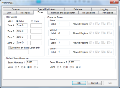
Screen 1‑6 Preferences Dialog Box: Zones Tab
Set zones using the following fields and options on the Zones tab in the Preferences dialog box:
|
Field/Option |
Usage |
|---|---|
|
|
|
|
Flaw Zones |
This section indicates the text label or layer name assigned to the flaw zones when the parts are created in CAD. Flaw zones in a part that are not labeled will be read as requiring perfect leather. |
|
Use |
The method used for labeling parts. Select Label if text labels and internal polylines are used to identify flaw zones; select Layer if flaw zone lines are identified by closed polylines lines placed on different layers. |
|
Zone A Label/Layer |
Type the text label/layer name that is used in a part to indicate that the part has an A zone. |
|
Zone B Label/Layer |
Type the text label/layer name that is used in a part to indicate that the part has a B zone. |
|
Zone C Label/Layer |
Type the text label/layer name that is used in a part to indicate that the part has a C zone. |
|
Zone D Label/Layer |
Type the text label/layer name that is used in a part to indicate that the part has a D zone. |
|
Zone lines on these Layers only |
Select this option if any parts in the job have internal polylines that are not intended to be zone lines. Type the layer(s) with the zone lines in the text box. |
|
Default Seam Allowance: |
This section determines the size of the seam allowance that CutWorks will apply to parts, and the severity of a flaw on which a seam allowance can be placed. You can apply more than one seam allowance, and each allowance can contain a different flaw zone. |
|
Seam Allowance 1 or 2 |
Type the amount of seam allowance that the CutWorks Software should apply to the inside perimeter of the parts. If two seam allowances are used, the larger seam allowance will be placed inside the smaller seam allowance. If no seam allowance is needed, type 0.00. |
|
Zone |
Select the flaw zone that will be applied to the seam allowance. |
|
Character Zones |
This section indicates the label text that is included in the parts to define the character zones, and the regions on a hide that a character zone can be placed. |
|
Label |
Type the text that is used in the part to label the character zone. |
|
Allowed Regions |
Select the region(s) that will accept a part containing the character zone. |
You must use the Set Part Zones command (click the Edit menu, then select the Edit Flaws and Regions command) to have the software read and interpret the zone information included in the CAD. Refer to paragraph 4.14.1 for more information on the Set Part Zones command.
Refer to the CAD Guidelines document contained on the CutWorks CD for more information on creating zones in CAD.
1.9.4 Remnant and Edge Buffer
The Remnant and Edge Buffer tab in the Preferences dialog box, shown in Screen 1-7, is used to set options for remnant calculation and edge buffers.
The remnant feature allows the software to determine how much usable hide is left after nesting parts onto a hide. After cutting the job, the remnant can be used for future production.
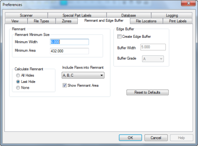
Screen 1‑7 Preferences Dialog Box: Remnant and Edge Buffer Tab
Set the options for remnant calculation using the following fields on the Remnant and Edge Buffer tab in the Preferences dialog box:
|
Field/Option |
Usage |
|---|---|
|
Remnant |
These fields define remnant dimensions and calculations. |
|
Remnant Minimum Size |
These fields determine the smallest area on a hide that can be considered remnant. In general, the lower you set these values, the more remnant appears. |
|
Minimum Width |
This value determines the narrowest section of remaining hide to be included in the remnant calculation. No piece of remnant will be narrower than this value. For example, if a piece of remaining hide is 6 inches wide, and this value is set to 12 inches, that section of hide will not be counted as remnant. |
|
Minimum Area |
This value determines the smallest area on the hide to be included in the remnant calculation. If an area of remaining hide is less than this value, it will not be counted as remnant. |
|
Calculate Remnant |
These options determine which hides to calculate the remnant for. |
|
All Hides |
Calculates the remnant for each hide in the job. |
|
Last Hide |
Calculates the remnant for only the last hide in the job that has parts. |
|
None |
The software will not calculate the remnant for any hide in the job. |
|
Include Flaws into Remnant |
Select an option from the drop-down list to determine which flaws, if any, to include in the remnant area. |
|
Show Remnant Area |
Select this option to turn on and off the blue lines (representing the remnant) that appear on screen. Note: Either the All Hides or Last Hide option must be selected for the blue lines to appear. |
|
Edge Buffer |
These fields determine whether an edge buffer is created and describe its characteristics. |
|
Create Edge Buffer |
Select this option to create an edge buffer. |
|
Buffer Width |
This value determines the width of an edge buffer. |
|
Buffer Grade |
This value determines the grade assigned to an edge buffer. |
|
Reset to Defaults |
Click this button to remove all customized settings and restore the CutWorks Software defaults. |
When the Show Remnant Area option is turned on, the remnant area appears as a series of blue lines. Also, the software displays two yields in the status bar: the first yield is based on the entire hide; the second (in parenthesis) is based on the used hide area, which is the hide area minus the remnant. See Figure 1-6.
Figure 1‑6 Hide with Remnant Displayed
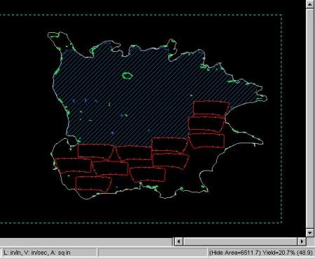
As parts are placed on or moved about on the hide, the software recalculates the remnant and updates the current yield and used hide area values on the status bar.
Note: There can be more than one remnant piece in the same hide, depending upon how the parts are placed on the hide and how the remnant options are set.
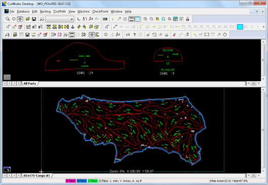
When the Create Edge Buffer option is turned on and then set in the Leather Nest Options dialog box, a hide edge buffer displays similar to that shown in blue. See Figure 1-7.
Figure 1‑7 Hide Edge Buffer
1.9.5 File Locations
The File Locations tab in the Preferences dialog box, shown in Screen 1-8, is used to define the location of specific files and directories. The files are used by the CutWorks Software when the database is used.
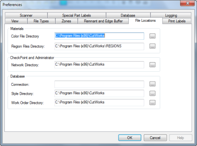
Screen 1‑8 Preferences Dialog Box: File Locations Tab
Set file locations using the following fields and options on the File Locations tab in the Preferences dialog box:
|
Field/Option |
Usage |
|---|---|
|
|
|
|
Materials |
Use this section to specify the locations of files needed to work with leather hides. |
|
Color File Directory |
Type the name of the directory that contains the Colors.cec file. This file stores information about the leather hide and flaw marking choices. |
|
Region Files Directory |
Type the name of the directory that contains the region template files. |
|
CheckPoint and Administrator |
Use this section to specify the location of the file that stores information about the privilege information set up for each user and administrator. |
|
Network Directory |
Type the name of the directory that contains the Radata.ceu file. |
|
Database |
Use this section to specify the locations of files and directories that are needed to properly record information in the database. |
|
Connection |
Type the directory and the file name for the database file. |
|
Style Directory |
Type the name of the directory that stores the styles used while working with the database. |
|
Work Order Directory |
Type the name of the directory that contains the Work Orders created and used while working with the database. |
 Instead of typing a directory or file path, click the Browse button located at the end of each file location text box to navigate to the directory containing the files.
1.9.6 Print Labels
The Print Labels tab in the Preferences dialog box, shown in Screen 1-9 is used to indicate that an optional label printer will be used with the CutWorks Software. The label printer would typically be installed on the cutting computer. A user would print the labels, which contain a picture of the part and any text associated with the part. The labels are then attached to the parts in a job and can be used later to identify the parts when they are sewn together.
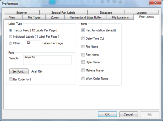
Screen 1‑9 Preferences Dialog Box: Print Labels Tab
Configure the label printer for use with the CutWorks Software using the following fields and options on the Print Labels tab in the Preferences dialog box:
|
Field/Option |
Usage |
|---|---|
|
|
|
|
Label Type |
Use this section to specify the type of label printer you are using. |
|
Tractor Feed |
A tractor-feed dot matrix style label printer is used. These labels usually come 12 labels to a sheet. |
|
Individual Labels |
A single-label printer in used. |
|
Other |
Another type of label printer is used. Contact Gerber Technology Technical Support for information on the type of printers and labels that are best suited for use with the CutWorks Software. |
|
Font |
Use this section to specify the font that will be printed on the labels. |
|
Sample |
This box displays a sample of how the text will look when printed using a selected font. |
|
Set Font |
Click this button to select the font name, style, size and effects. |
|
Bar Code Font |
Select this option to print the labels with bar code information. |
|
Items |
Use this section to specify items that will be printed on the labels. |
|
Part Annotation (default) |
Select this option to print the labels with part annotations. |
|
Date/Time Cut |
Select this option to print the labels with date and time cut information. |
|
File Name |
Select this option to print the labels with the file name. |
|
Part Name |
Select this option to print the labels with part names. |
|
Style Name |
Select this option to print the labels with the style name. |
|
Material Name |
Select this option to print the labels with the material name. |
|
Work Order Name |
Select this option to print the labels with the work order name. |
Once you have configured the label printer for use with the CutWorks Software, use the Print Labels and Print Kit Group commands on the File menu to print the labels and kit group. Refer to paragraph 2.7.5 for more information on this command.
1.9.7 Scanner
The Scanner tab in the Preferences dialog box, shown in Screen 1-10 is used to indicate which COM Port (on the computer) has a bar code scanner attached. Customers can use a bar code scanner to enter information into the CutWorks Software. Any computer running the CutWorks Software can be configured to accept scanner input, however, the scanner would typically be installed on the computer used to process job files—typically this is the cutting computer.
The scanner must be physically installed (according to procedures provided with the scanner) into an available COM Port on the computer. Once this is done, use the Scanner tab in the Preferences dialog box to indicate the COM port used by the scanner.
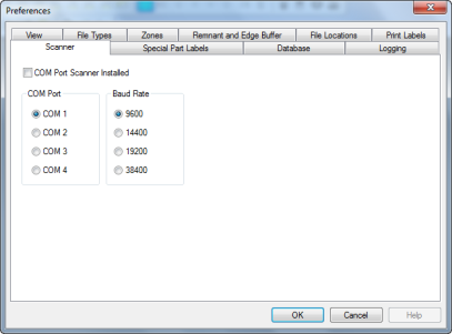
Screen 1‑10 Preferences Dialog Box: Scanner Tab
Configure the CutWorks Software for scanner input using the following fields and options on the Scanner tab in the Preferences dialog box:
|
Field/Option |
Usage |
|
COM Port Scanner Installed |
Select this option to indicate that a scanner is installed. |
|
COM Port |
Select the COM Port that the scanner is installed on. |
|
Baud Rate |
Select the baud rate for the scanner. |
Once the software has been configured to receive scanner input, you can configure the following dialog boxes for use with the scanner:
-
User Log On
-
Fast Open Work Order
-
New Work Order
-
Add Material Instance
To configure a dialog box for scanner input:
-
Open the dialog box you want to configure. On the title bar of the dialog box, click the bar code scanner button at the right to switch to Configure Scanner mode. The fields that can be configured for scanner input will contain text in blue, as shown in Figure 1-8.
Figure 1‑8 Configure Scanner Dialog Box

-
Click on the fields in the order that you want to scan bar code information.
The text in the field will change to “Scanner 1”, “Scanner 2”, etc. using consecutive numbers to indicate the order for scanning. By sequencing the fields, the scanner will input the information in one field and then automatically go to the next. -
Or you can right-click on the blue text to change the field to “Not Assigned.” If a field is Not Assigned the cursor will not automatically jump to the field for bar code input. You can manually click on the field at any time to scan information for the field.
-
On the last field that will be scanned for bar code input, press the Ctrl button on the keyboard and click the mouse to change the field to Scanner + END. This will input the bar code information for the last field and accept all the other information in the dialog box (as if you clicked the OK button). You can use this function even if the dialog box only contains one field for bar code input.
-
Press the Esc button on the computer keyboard to exit Configure Scanner mode. All configuration information will be saved.
1.9.8 Special Part Labels
When a part is created in CAD, a text label can be used to identify the part as a special part. A special part may have been:
-
Assigned an AutoNest priority
-
Defined as a welt
-
Assigned an orientation constraint
Refer to the CAD Guidelines document contained on the CutWorks CD for more information on how to create special parts in CAD. Then use the Special Part Labels tab in the Preferences dialog box, shown in Screen 1-11, to indicate the text label and layer name used in the CAD to define the nesting priority, welt, and orientation constraint.
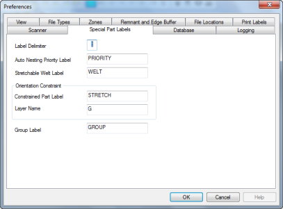
Screen 1‑11 Preferences Dialog Box: Special Part Labels Tab
The Special Part Labels tab in the Preferences dialog box contains the following fields:
|
Field |
Usage |
|---|---|
|
Label Delimiter |
Type a character to assign as delimiter for label data. |
|
Auto Nesting Priority Label |
Type the label used in the CAD to define the AutoNest priority. |
|
Stretchable Welt Label |
Type the label used in the CAD to define the part as welt. |
|
Orientation Constraint |
These fields are used to indicate the label and layer used in the CAD to define orientation constraint. |
|
Constrained Part Label |
Type the label used in the CAD to indicate the part must follow orientation constraints. |
|
Layer Name |
Type the CAD layer name that includes the grain lines that define the orientation constraint to apply to each part. |
|
Group Label |
Type the label used to designate a group. |
When you open a job that includes special parts, you must use the Interpret Labels command (click the Edit menu, then select the Edit Parts command) to have the software read and interpret the label information included in the CAD. Refer to paragraph 4.13.5 for more information on the Interpret Labels command.
Also, when a part includes an orientation constraint, refer to paragraph 5.5.1.4 for important information.
1.9.9 Database
Use the Database tab in the Preferences dialog box, shown in Screen 1-12, to select the options to apply to all work orders as they are opened.
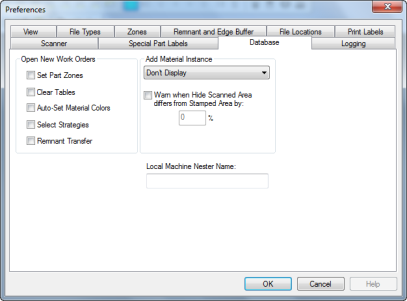
Screen 1‑12 Preferences Dialog Box: Database Tab
Set database preferences using the following fields and options on the Database tab in the Preferences dialog box:
|
Field/Option |
Usage |
|---|---|
|
|
|
|
Open New Work Orders |
These options specify how a work order will appear on the desktop when a new work order is opened. |
|
Set Part Zones |
Select this option to have the software read and display the flaw and character zone information included in the work order. |
|
Clear Tables |
Select this option to have the software remove all parts from any tables in the job, leaving just the master parts. |
|
Auto-Set Material Colors |
Select this option to have the software apply a symbolic color to a table based on the material type(s) used in the work order. |
|
Select Strategies |
Select this option to display the Select Strategies for Network Nesting dialog box when the work order opens. |
|
Remnant Transfer |
Select this option if a remnant of a hide remains on the cutting table and will be used for the first hide on a work order without scanning it again. |
|
Add Material Instance |
These options specify how Add Material Instances are handled. |
|
Drop down box for displaying |
Select an option for displaying Add Material Instances. Choose one of the following: Don’t Display (default), After Cut, or Before Scan (Taurus Only). |
|
Warn when the Hide Scanned Area differs from Stamped Area by: |
Type a value for allowable percentage (%) difference between the Hide Scanned Area and the Stamped Area. |
|
Local Machine Nester |
The name of the computer you are using. This name is assigned when the nester is added to the database and cannot be changed here. |
1.9.10 Logging
Use the Logging tab in the Preferences dialog box, shown below, to select how CutWorks writes to the Windows log file called CutWorksLog. Options in this tab set the level filters used determine which log entries are sent to and stored by the CutWorksLog service.
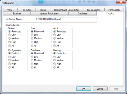
Screen 1‑13 Preferences Dialog Box: Logging Tab
Set logging preferences using the following fields and options on the Logging tab in the Preferences dialog box:
|
Field/Option |
Usage |
|---|---|
|
Log Server Name |
Type the name of the local server where log data will be written. |
|
Logging Levels |
These options allow you to set filter levels for data logging for various CutWorks activities. |
|
System |
For System data select: Restricted, Low, Medium, High, or All. |
|
Error |
For Error data select: Restricted, Low, Medium, High, or All. |
|
Audit |
For Audit data select: Restricted, Low, Medium, High, or All. |
|
Configuration |
For Configuration data select: Restricted, Low, Medium, High, or All. |
|
Database |
For Database data select: Restricted, Low, Medium, High, or All. |
|
Nesting |
For Nesting data select: Restricted, Low, Medium, High, or All. |
1.10 Working with Windows
The following cursor and mouse operations are unique to the CutWorks Software.
-
Click the right mouse button on the selected data to modify existing data in some text boxes.
-
To zoom in, position the cursor in the upper left-hand corner of the area you want to view. Then click and hold the right mouse button and drag the cursor diagonally to form a window in the area that you want to view. When you release the right mouse button, the area enclosed by the rectangle is enlarged to full screen. You can use this method to enlarge an area several times so that you can view detailed entities of the job such as notches.
-
To de-select all entities that have been selected, click the left mouse button.
-
When the mouse pointer passes over different parts of the job, it changes shape, indicating what it will do at that position (refer to Figure 1-9).
-
Use the mouse button and keyboard to move, flip, and rotate parts (in the optional nesting modules).
A list follows explaining all the cursors that appear in the CutWorks Software.
Figure 1‑9 Mouse Pointer Shapes and Meanings
|
Pointer Shape |
Usage |
|---|---|
|
|
This pointer appears in all modules. Use the pointer to choose a menu and command, click a toolbar button, and to select options in dialog boxes. |
|
|
This pointer appears in all modules. It is displayed when using the mouse to zoom in on a selected area. |
|
|
This pointer appears in all modules. It is displayed in dialog boxes containing columns that can be adjusted. When the pointer changes to this symbol, drag the column heading to the left or right to resize the column. |
|
|
This pointer appears in all modules. It is displayed when a column is hidden in dialog boxes containing columns that can be adjusted. When the pointer changes to this symbol, drag the column heading to the right to expand the hidden column. |
|
|
This pointer is used in the Base Module to select entities and groups of entities in the marker. |
|
|
This pointer is used in the ToolPath Module to select the order and direction of entities and groups of entities to be processed in the job. |
|
|
This pointer is used in Nesting Mode to select parts and groups of parts in the marker. |
|
|
This pointer is displayed in the Nesting Mode to indicate the direction of movement when dragging or shooting parts. |
|
|
These pointers are displayed when the pointer is moved over the border of the Bird's Eye or Master Parts child window. Use these pointers to drag the border to resize the window vertically, horizontally, or diagonally. |
|
|
This pointer appears when using the Intellimouse to pan or zoom. |
|
|
This pointer appears when in Edit Flaws and Regions mode. Use this pointer to resize a displayed region template. |
|
|
This pointer appears when in Edit Flaws and Regions mode. Use this pointer to select flaws for editing. |
1.11 Find Help
The CutWorks Software uses the standard Windows online help format. Online help is a convenient way to look up information about a concept, command, or dialog box.
For additional information about online help, click the Help menu, then select the How to Use Help command. The Windows Help dialog box appears.
1.11.1 Help Contents
To view the general help contents:
-
Press F1 with the CutWorks desktop displayed, or click the Help menu, then select the Contents command. A list of help topics appears in a separate window.
-
Click any green underlined topic in the list. Depending on the topic selected, either a list of relevant topics appears, or information about topic that you selected is displayed on the screen.
-
If a topic is not listed, click the Index button to search for the topic. The Help Topics dialog box appears.
-
Scroll through the list or type the first few letters of the topic you are looking for.
-
Select a topic from the list and click the Display button. Or, double-click the topic in the list. A new window is displayed that discusses that topic. Depending on the topic, the window might contain text and/or an image. Click the areas of the image or the green underlined text to view additional information.
1.11.2 Help with a Dialog Box
To obtain help for a specific dialog box:
-
With a dialog box displayed, press the F1 key on your keyboard. A new window appears that contains a description of that dialog box. Depending on the dialog box, the window might contain text and/or an image.
-
Click the areas of the image or the green underlined text to view additional information.
1.11.3 Search for a Help Topic
The Find feature is an efficient way to search for the information you need. To search for a Help topic:
Press F1 with the CutWorks desktop displayed, or click the Help menu, then select the Contents command.
-
Click the Find button at the top of the help contents window. The Find Setup Wizard dialog box might appear. Follow the instructions in the wizard to create the search list. When done, the Help Topics dialog box appears with the Find tab active.
-
Type a word or phrase in text box 1. A list of topics that contain the word or phrase appears in text box 3.
-
Double-click word or phrase in text box 3. Information about topic that you selected is displayed on the screen. Depending on the topic, the window might contain text and/or an image. Click the areas of the image or the green underlined text to view additional information.
CHAPTER 2


