Avatar
The Avatar panel provides functions to edit body positions and view the avatar in Blender.
Available Avatars:
-
USPlus18 - A-Pose to arms-down
-
USPlus24 - A-Pose to arms-down
-
UScurvymissy02 - Contra (casual), Driver, A-Pose
-
UScurvymissy06 - Contra (casual), Driver, A-Pose
-
UScurvymissy14 - Contra (casual), Driver, A-Pose
-
USMale34 - Contra (casual), Driver, A-Pose
-
USMale40 - Contra (casual), Driver, A-Pose
-
USMale46 - Contra (casual), Driver, A-Pose
-
USMale52 - Contra (casual), Driver, A-Pose
-
USMale58 - Contra (casual), Driver, A-Pose
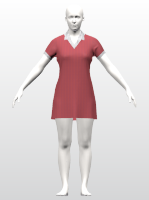
 Body Positions
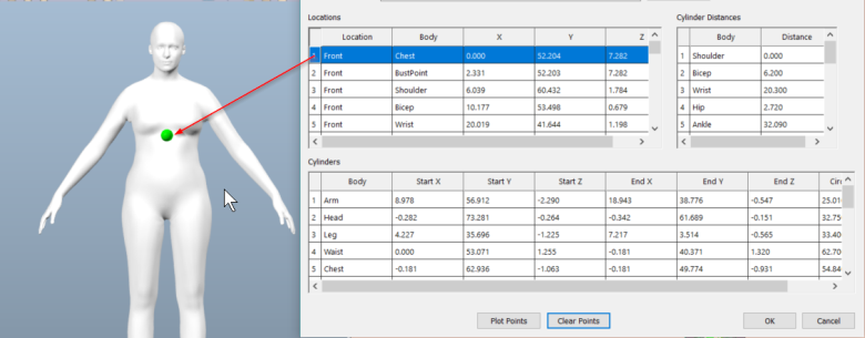
Use to display the piece positioning information for the selected avatar. Body positions define the location relative to the avatar for piece placement. The Avatar Body Positions Grid identifies these locations and cylinders. Once a location or cylinder is selected, the specified area is highlighted on the body in the Avatar window. These points can easily be selected and moved to a user defined placement.
The Body Positions map the piece to the body position. When new avatars are created, use the body positions to make adjustments to the map points directly on the avatar.
Edited cylinders are saved with individual models. Edited Body Positions are used every time an avatar is applied to a new model.
To View/Edit Body Positions:
-
From the 3D tab, select Body Positions in the Avatar panel.
-
Select the Location, Cylinder or Cylinder Distance you would like to edit
-
If an item in the Locations form is selected, a green dot will appear on the avatar to indicate the placement of that location. Left click to select the dot. Move the cursor to move the selected green dot. Left click again to release, fixing the dot to the new location.
-
If an item is selected in the Cylinders form, a transparent cylinder will appear on the avatar. The cylinder is anchored with six (6) cones. The red cone should always represent the bottom of the cylinder. To adjust the cylinder, left click a cone and cylinder will adjust as you move the cursor. Left click again to release, fixing the piece to the new location.
-
Use the cones at the top and bottom (red) to relocate or change the angel of the cylinder.
-
Use the cones placed about the center of the cylinder to make it wider or narrower.
-
-
If an item in the Cylinder form, a green halowill appear around the cylinder. Left click to select the bangle. Move the cursor to slide the bangle along the cylinder. Left click again to release, fixing the bangle to the new location.
-
To enter measurements, click inside of the cell desired cell in the form and manually enter a value.
-
Once all desired measurements are defined, select OK.
-
When asked if you would like to “Save Avatar Position Changes”. Click Yes to save the new body positions.
 Avatar Editor
Use to launch Avatar Editor to upload and /or customize a new avatar.
The Avatar panel provides functions to view and edit Avatar in Blender.
The Avatar Editor feature allows users to edit an avatar from a library of avatars or import third party body scan (.obj) avatar files.
To launch Avatar Editor:
1. Open Pattern Design (a model or piece does not need to be open)
2. Navigate to the 3D Tab
3. Under the Avatar Tab, click on the icon Avatar Editor a separate blender window will open.
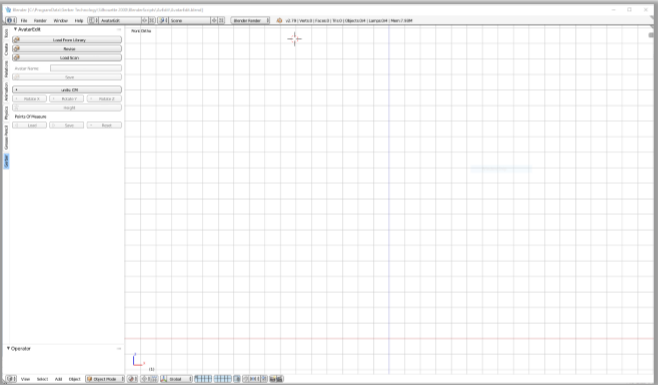
Note: Users can access the Avatar Editor Icon from the Avatar Tab in the 3D Workspace when a model is open in Pattern Design.
Open Avatar
Once the Avatar Editor icon is selected, the Avatar Editor will launch On the left side of the workspace is a toolbar. At the top there are three options to load avatars; Load from Library, Revise, or load from scan.


1. Load from Library will launch a library or directory of base avatars that are installed with AccuMark and can be edited with the Avatar Editor.
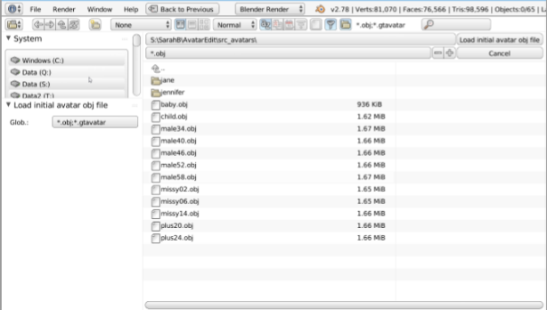
a.The file path is C:\ProgramData\Gerber Technology\Silhouette 2000\BlenderScripts\AvEdit\src_avatars\
jane (must open sub-folder to access .obj file) hair is only in short length for Avatar Editor
jennifer (must open sub-folder to access .obj file) hair is only in short length for Avatar Editor
baby male34 male46 male58 missy06 plus20 child male40 male52 missy02 missy14 plus24
b.Any version of Jill or Stan are not supported in the v11.1 Avatar Editor.

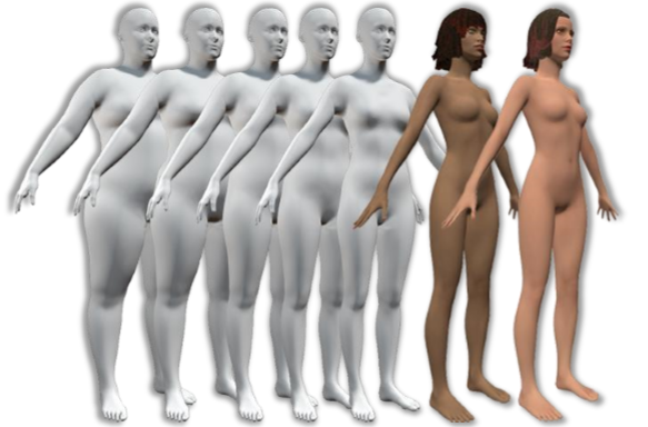
Plus24, plus20, missy06, missy02, jennifer, jane

Baby, child, male34, male40, male46, male52, male58
c. After desired avatar is selected left click Load Initial avatar obj file button
2. The Revise button will launch a window to display the avatars sub-folder of the Silhouette 2000 folder on the users system. All avatars in the folder will display but only the avatars previously edited using the AccuMark 3D Avatar Editor will load.
a) Select desired avatar or .obj. Left-click Load a previously edited GTAvatar.
3. The Load Scan button will launch a window to the users “My Documents” path to access .obj body scan avatars.
a) The user will be able to navigate to other folders on their system if the file is stored in a different folder.
b) The path is sticky and will launch to last directory location a scan loaded from.
c) For more information on third party body scan avatar requirements please refer to Loading in Third Party .obj Avatar Files.
d) Choosing input units:
i) After selecting the avatar to edit a dialog box opens to choose the correct input file units. The input units set the scale of the avatar; choose the unit that corresponds to the correct avatar size (height). The system attempts to detect the unit of measure the .obj file is in upon import and converts it to the Avatar Size. The default units for Avatar Size will be in CM. After using the Avatar Editor for the first time, the next time the program is launched the units for Avatar Size will be the last units worked in (CM or IN). 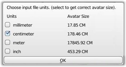
ii) This step is critical in ensuring that the scale of the avatar is correct when bringing in an .obj avatar from a third party.
iii) This dialog will not display for base avatars loaded from the library as their scaling is already correct.
iv) This dialog box only appears upon initial import. After the scaling is set and saved, it will no longer appear.
4. Units:
a) A radio button displays the unit workspace is in currently. The default in metric (CM).
b) To change to imperial (IN). Left-click the units’ button to toggle between units CM to units: IN.

Note: the units’ button is sticky and the workspace will remain in the unit it was last worked in.
5. Rotation:
a) Use the Rotate X, Y, Z buttons to rotate the avatar in the workspace upon loading if the avatar is not correctly oriented. Often third party body scan avatar files are loaded upside down or backwards.
b) Rotate to ensure the avatar is head up and forward facing.
c) It is not necessary to rotate avatars from the base library as they are already in the correct orientation.

6. Users can use the Load Scan to import an .obj file, enter a name for avatar, and save. This will generate the .gtavatar file as well as the other associated files needed to use the avatar with AccuMark 3D. Users do not need to load the points of measure or make any additional changes in the Avatar Editor platform.
Adjusting Height
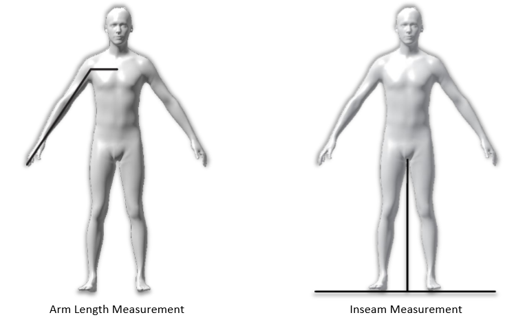
Once the avatar is loaded and orientation is head up and forward facing, the next step to adjust the overall height of the avatar. In AccuMark Avatar Editor, height is measured from the floor to the top of the head straight through the center of the body. 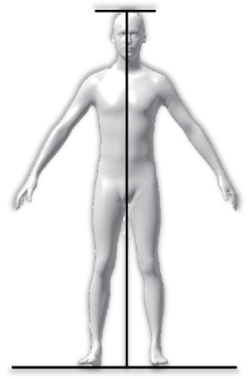
Left –click on the Height button to begin
1. A dialog box will open to adjust the height of the avatar. Adjusting the height using this button allows for a proportionate adjustment to entire body
a. Inseam can also be adjusted at the same time by using the slider buttons or typing in the value using a numeric keypad.
b. A check box allows the user to enable/disable arm scaling with the height adjustment. If the box is unselected or disabled, the user can enter a value into the ArmLength field. * It is highly suggested that the total arm length adjustment be made at this stage in the edit so that the length is evenly distributed throughout entire length of arm.
c. Scaling of circumference measurements with height adjustment is enabled/disabled via a check box.
d. After choices and changes are made in height box select OK to exit the dialog box.
e. The changes automatically update to the avatar. Note: this is the only occasion measurement changes update automatically.
Points of measure
After the height is defined, the next step in the avatar editor is to load the points of measure (POM). POM is visualized with an anchor and landmark. The anchor is the round sphere to the left of the POM name. The landmark is the circumference line around the avatar at the anchor position. Loading the POMs is required before measurements can be adjusted.
The points of measure and associated lines are calculated as the avatar is brought into the program. The avatar is broken into four limbs and torso (torso includes the head). The POMs are distributed evenly on the associated body part/limb proportionately. For the torso and legs, the POMs are calculated straight up from the floor through the center of the body. The POMs for the arms are distributed proportionally from the armscye ends of finger tips, straight through the center of the arm.

1. Select the  button under the Points of Measure section to populate the POMs.
2. Pre-defined POMs will populate onto the avatar. The name and the measurement of each POM will display to the right of the anchor.
a. The measurements are listed in the measurements chart in the toolbar panel on the left but are greyed out since editing measurements are not allowed in this step of the process
3. Once the POMs are loaded, an expanded Points of Measure section in the toolbar displays.
4. POM names and values can be shown or hidden. The POMs can be toggled on or off throughout the editing process.

5. There are three sections of POMs to adjust; Torso, Leg and Arm.
a. The Torso includes the head, neck, trunk all the down to the hip. If an adjustment needs to be made to the upper leg, use a torso measurement for the best blending result.
b. The Arm starts at the armpit and ends at the fingertips. The arm length is measured from center back between the shoulder blades to end of fingertips through the center of the arm.
c. The Leg starts at the top of the inseam and includes the foot.
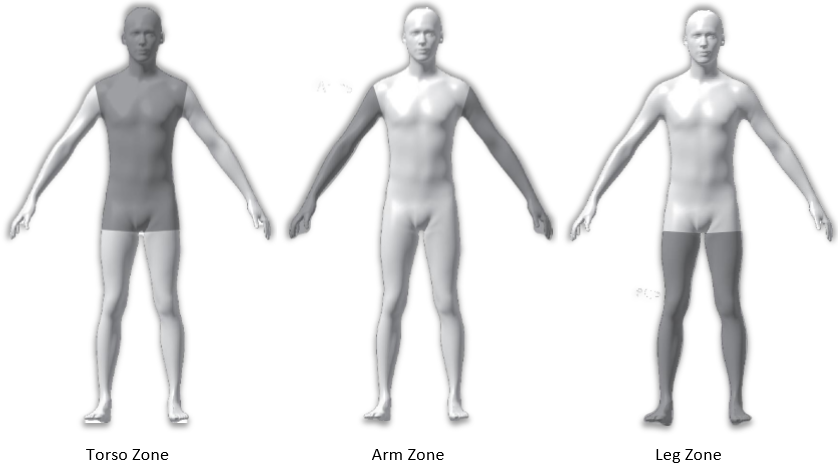
d. To Add a POM line:
i. Select Torso, Leg, or Arm in the row next to Add.
ii. The avatar will rotate to a forward facing view and the 3D cursor will appear on the avatar. Move the cursor along the body to desired position. Users can use the middle mouse wheel to rotate the avatar. Left-click to place.
1. For the arm and leg the 3D cursors will snap to the wearers right limb (left side of screen).
iii. A dialog box will appear to name the POM line. Give the POM a name and Click OK.
1. The new POM landmark is placed on the avatar. The name and circumference measurement are also placed and temporarily highlighted in green.
2. In the POM table, the new POM is added to display the circumference measurement, the distance from floor, and depth divided by width (the ratio of the thickness to the width).
iv. Repeat this process to add additional POMs.

g. Notes on Points of Measure:
i. To find points of measure on a human in a live fitting, we use bones as landmarks. Avatar’s have no underlying skeletal structure so there are no bones to use as landmarks. To compensate AccuMark 3D measures the shoulder width from the underarm to underarm. It is fixed landmark and cannot be deleted or moved, however the measurement can be adjusted to be wider or narrower.
ii. POMs added below the neckline and above the shoulder width/armpit level are added as circumference POMs, not straight horizontal measurements.
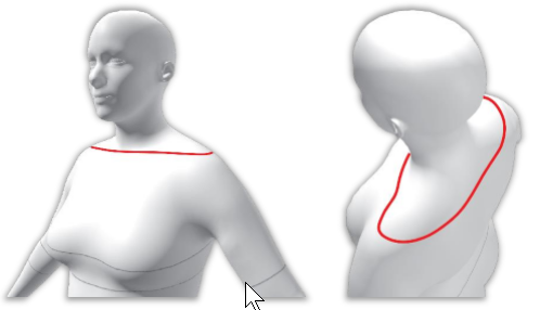
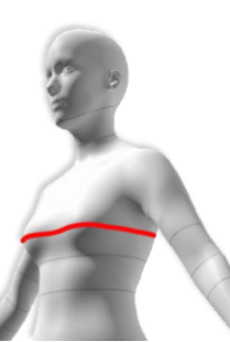
iii. Chest/Bust is measured across the breasts straight and does not measure the curved space between the breasts even though visually the landmark is curved between the breasts.
6. Use the Save button under Points of Measure to save the current POM set up (names, locations of POMs on the avatar). Saving the POMs allows for these POMs and landmarks to be loaded on all future base avatars that are loaded from the library on the users system.
a. The POMs can be reset to the default configuration by selecting the Reset button.
b. Once all POMs are displayed and in desired location select the  button to begin the circumference
editing
Edit Points of Measure Values
Now that all the desired POM landmarks are placed on the avatar the next step is to adjust the circumference measurements.
As points of measure values are adjusted the system smooths the avatar’s body based on the POMs active or disabled state.
1. Activate all POMs and change all the values.
a. All POMs will be changed and avatars shape will be adjusted seamless accordingly.
2. Activate all POMs but only change some of the values.
a. The POMs that were adjusted in value will update to their new size. The POMs that were activated but NOT changed will remain their original value/size. Upon selecting the resize button, the system will create a smooth transition between these POMs.
3. Activate only the POMs intended to change in value, the rest are disabled.
a. The POM that is activated and changed in value will update to its new value and size upon selecting resize.
b. The balance of the POMs will automatically scale with the new change in value to create a smooth transition between all POMs.
c. This is useful for when a landmark is desired on an avatar but the user does not have a specific body standard to assign to that POM.
4. Any measurement changes to the circumference, height or depth/width columns when a resize is performed will result in deactivated POMs to change.
a. I.e. if a resize is needed to only the depth/width column, the user must still activate all the POMs they want to keep exactly as is, otherwise they will scale.
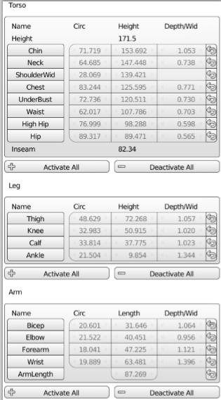
To edit the points of measure values:
1. Left-click into the Circ. (circumference) column next to the point of measure. Enter a value using the numeric keypad.
a. To use the slider function left-click + hold and slide mouse to right to increase measurement and left to decrease measurement.
2. For changes to update on to the avatar, click the Resize button. Changes will not automatically display on the avatar.
3. To reset a POM back to the default value select the button in the far right column of desired POM row. The value in the table will change back to default value. Left-click the Resize button to update the change to the avatar.
a. Each individual POM can be reset to back to default without changing the balance of the measurements except for height and inseam, these can only be reset using the height function button.
b. The default value is the measurement that is loaded from disk when an avatar is loaded from the library or the most recent scaling value from the height function.
c. To reset to original default if the scaling from the height function was used, the user will need to re-run the height function.
4. Weight distribution can be adjusted in the table using the Depth/Wid. Column, HOWEVER it is defined as the depth or thickness divided by width. It is evenly distributed left to right or back to front. It cannot distribute more weight to one side other another or more to the back versus the front.
a. While the maximum value is 4.000 and the minimum is 0.250, small changes in the ratio have a big impact on the distribution of the weight.
b. Below is an example of the weight distribution for the base avatar jane’s hip measurement. Her hip measure 88.380 cm with a system default depth/width of 0.562. Any changes to the ratio keeps the circumference the same but changes the fullness.
i. Increasing the ratio to 0.652 moves the fullness more to the front and back of her hips creating at narrower appearance from the front view.
ii. Decreasing the ratio to 0.502 moves the fullness more to the sides of her hips creating a wider appearance from the front.
iii. Remember: the distribution is evenly moved from front/back to the left/right sides. Review the side view and notice how the front of hip convex and concaves with change is distribution.

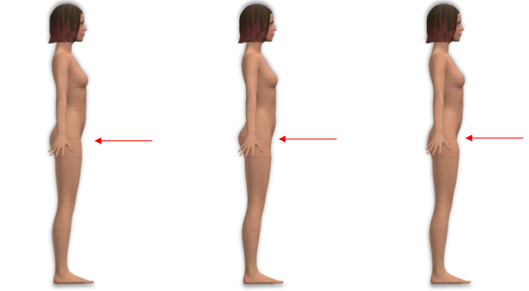
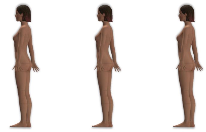
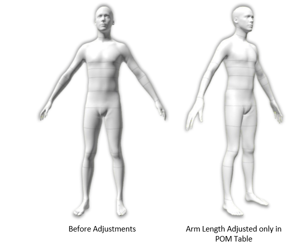
5. If the height, inseam or arm length needs to be adjusted further, use the Height button and dialog box for adjustments. Resizing the arm length by only adjusting the measurement in the POM table increases/decreases the arm length but the measurement are not evenly distributed throughout the length of the arm but rather concentrated to arm.
Avatar Color
Avatar Editor now has the ability to make a change to the surface color of the avatar. The skin color of Jane & Jennifer are skin textures and more complex than a single color; these avatars cannot be customized for color at this time.
The Avatar Color box will populate below the rotate buttons after points of measure are loaded.
1. Left-click into the color box to the right of text Avatar Color.
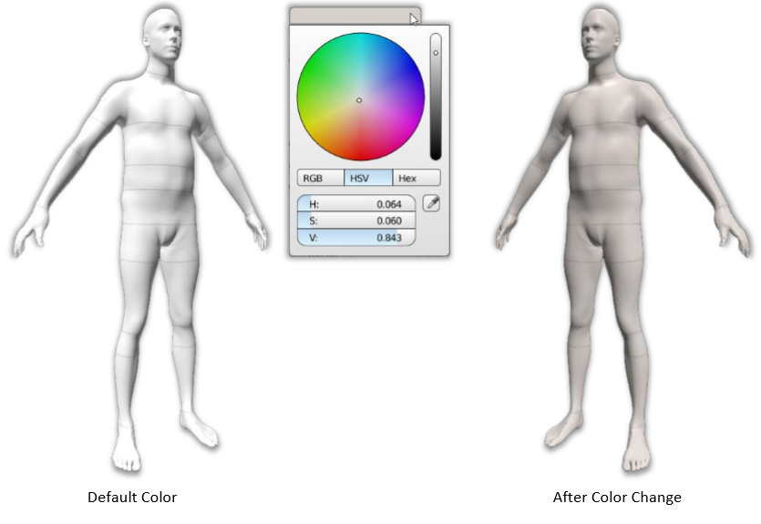
2. A color selector box will launch.
a. A rainbow color wheel & hue slider is available to choose color.
b. Color can be selected and entered via RGB, HSV or Hex values using either slider or numeric keypad entry.
c. For different avatar colors enter the following numbers into the HSV values:
i. Baby and Child’s default color is a taupe Grey.
ii. The v11 avatars default avatars with a prefix of U default color is White.
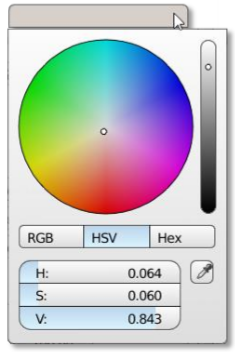
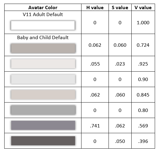
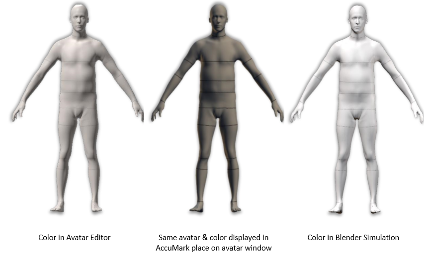
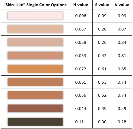
d. Avatar Color is not meant to represent a "skin" tone. Skin has depth, texture, dimension, and color to create its appearance. The avatar color is more comparable to store mannequin's color and not a skin tone. We do not recommend using the avatar colors if you are trying to achieve life-like appearance. In AccuMark Avatar Editor, users can only select a single color to represent their avatar. Below is a sample of possible skin-like single color options.
3. once a color is selected the avatar will automatically change color and the color ox will update with the chosen color.
Saving Avatar Edits
Saving the edits to the Avatars allows the avatar to be used in AccuMark 3D.
1. After all edits are made, including circumference and color changes, Left-click into the blank field next to Avatar Name and begin typing desired name.
2. Any spaces added into the name will be replaced with underscores in the directory (i.e. Male 34 Med Grey will become Male_34_Med_Grey).
3. Once text is in the field, Left-click into the workspace or strike Enter on the keyboard. The Save button will activate to enable saving.
Note: there is no auto save with Avatar Edit. All changes must be saved manually
4. The newly saved Avatar is now saved in the Avatar Directory in the Silhouette folder on your system: C:\ProgramData\Gerber Technology\Silhouette 2000\Avatars a. The avatar is saved with the file extension .gtavatar
b. Additional files created automatically upon saving include the body positions, inflate and met files.
5. If you have saved and continue to make edits without exiting the Avatar Editor then proceed to Save without changing the avatar name the user will get a confirmation that the Avatar Name already exists and to confirm overwriting.
6. To save an avatar that has been edited and re-loaded into Avatar Editor with the same name the name in the Avatar Name field must appear exactly as it is in the Avatar Directory when originally saved. The name does not automatically populate into the name field as to prevent accidental overwriting of file names.
Loading in Third Party .obj Avatar Files
The avatar edit platform allows for third party .obj avatar import. Please note the following in order for the program to process the avatar.
-
Format must be .obj
-
Avatar must be closed object (watertight)
-
Avatar must have a head, arms/hand, and legs/feet
-
Hands to be in oriented in same position left to right
-
Hands positioned farther out from body than feet
-
Arms can be in different poses (up, down, side: A pose or T pose)
-
Symmetrical is preferred however arms & legs will be made symmetrical at points of measure input/edit
-
Avatar should be centered, feet should straddle x=o
-
Arms & Legs should be as straight as possible (not a bend pose)
Using A New Avatar in AccuMark 3D
The avatar that was created and edited or adjusted in the Avatar Editor once saved will be located in the Avatar Directory located C:\ProgramData\Gerber Technology\Silhouette 2000\Avatars. To use your new avatar:
1. Open 3D in Model Editor or 3D Workspace and change avatar normally.
2. In the Avatar Window in AccuMark the avatar will show the new color (if changed) and display the POM lines. Note: that the color may look different than it did in AccuMark 3D viewport as Blender as better lighting.
