Pattern Design: 2D
Fabric images can be defined in the model editor and further enhanced in Pattern Design to add trim details like buttons and logos along with stitching to simulate a complete garment. This section will take an in depth look at working with images and other 2D features that will enhance the 3D simulation.
Getting Started in Pattern Design
This section will briefly review the screen layout within Pattern Design in order to prepare patterns for 3D simulation. The first step is to learn the different screen elements and how to open files.
Opening Pattern Design
To Launch the Pattern Design Program:
-
Double click the Pattern Design icon located on the Desktop.
Default Storage Area
The default storage area defines what settings should be used for working in Pattern Design. This storage area also serves as the default location for saving files. This setting would need to be changed if the wrong Unit of Measure was displayed in the Info Bar (IMP / MET).
To Change the Default Storage Area in Pattern Design:
-
From the Edit tab, select the Customize dropdown and then Preferences in the Workspace panel. A dialog box displays.
-
Select the Paths tab at the top of the dialog box.
-
Enter the correct data for the following fields:
-
Device – select the drive letter where the storage area resides.
-
Storage Area – select the Storage Area name.
-
Select Save. Select OK to close the Preferences dialog box.
 Open
Open
Use this function to retrieve pieces or models from an AccuMark storage area.
To Open Data:
-
From the File menu, choose Open or press the Ctrl + O keys on the keyboard.
-
In the Files of Type field, click on the down arrow to select the data type to open.
-
In the Look In field, click on the down arrow to select the device and/or storage area where the pieces or models are stored.
-
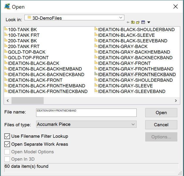
To shorten the list of data displayed type part of the style number in the File Name field. For example, to find all pieces that start with 100, type 100* into the File Name field and press Enter or click Open. The * serves as a wildcard, meaning the pieces must start with 100, but can have any other characters after that number.
-
Select the item(s), listed in the window. Multiple files can be selected using the Shift or Ctrl keys.
-
Click on the Open button and the pieces will appear in the icon bar.
The following options can also be used when opening pieces or models:
-
Use Filename Filter Lookup – allows the user to view filtered file names only. A wildcard filter must be typed into the file name box before any file names are displayed. Once the filter is typed in, the Enter key or the Open button can be used to display the filtered list of file names.
-
Open Separate Work Areas – select this option to open the retrieved file into a new work area. Leave this option unchecked to open the file into the current work area.
-
Open Model Options – allows for the additional pieces listed in Model Options to be opened along with the model.
-
Open in 3D – if a model is already prepared with correct seam placement and images, it can be opened directly in Pattern Design 3D to create sewing relationships and check piece placement.
To Place Pieces in the Work Area
-
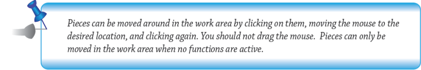
To place pieces individually, click on the desired piece in the icon bar. Click again in the work area to place the piece.
-
To select and place multiple pieces, use one of the following methods:
-
Click and drag with the left button across the desired pieces and then press the Space Bar or click on one of the highlighted pieces to place the pieces in the work area.
-
Select multiple consecutive pieces by first holding down the Shift key and clicking on the first and last piece of the group, then press the Space Bar or click on one of the highlighted pieces to place the pieces in the work area.
-
Select multiple, non-consecutive pieces by first holding down the Ctrl key and clicking on the desired pieces, then press the Space Bar or click on a highlighted piece to place the pieces in the work area.
4. Select pieces using a method above and select right mouse button/Place Positioned.
Screen Elements
-
Title Bar is located at the top of the Pattern Design window. It consists of three icon buttons and a quick access toolbar:

The title bar buttons are located on the far right of the title bar. The program can be restored, minimized, maximized or closed using these buttons.
-
The Minimize button is the first button on the far right of the title bar. Use this button to shrink the Pattern Design window down to a button on the Task Bar.
-
The Maximize/Restore button is the second icon on the far right of the title bar. Use this to change the size of the window to full or partial screen.
-
The Close button is the third icon on the far right of the title bar. Use this to exit the Pattern Design program.
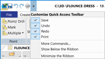
The Quick Access Toolbar is located on the far left of the title bar. This customizable toolbar provides the ability to access functions with a single click. By selecting the control below, a drop down menu of the default options will display. To add additional commands to this toolbar, select “More Commands…”
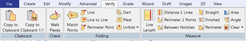
Ribbon command is a modern interface to make it easier to locate functions and be more productive. With the ribbon, functions are grouped in Tabs which include the File menu, Create, Edit, Modify, Advanced, Verify, Grade, Wizard, Draft, 3D, and View.
-
Toolbar is located below the ribbon. This can be the default toolbar or your own customized tool bar. Toolbars can be repositioned in the application windows.

-
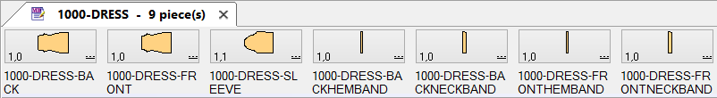
Piece Icon Bar at the top of the screen. The icon bar consists of opened pieces or models. The Piece Icon Bar can be repositioned in the application window.
-
Work Area is located in the center of the screen. This is where all of the pattern making functions will take place.
-
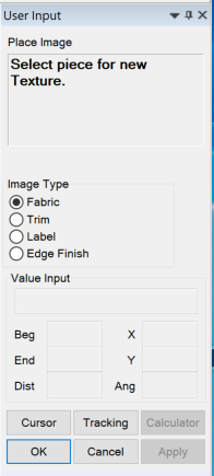
User Input Box is located on the far right of the screen and provides interactive communication between the user and the Pattern Design program. In this box, a prompt is displayed, options can be changed for different functions and measurements can be input.
-
The name of the function currently being used.
-
Prompt Box – directions to perform the next step in a function.
-
Options Area – allows the user to customize a function. This area can contain radio buttons, check boxes and other fields to change the way a function works.
-
Value Input section – fields for typing in piece names and measurements when using Value Mode.
-
Buttons – use to perform the following functions:
-
Cursor/Value button – switches the mode the Pattern Design program is working in. Cursor allows the user to move things by eye; Value allows the user to type in exact measurements.
-
Tracking button – activates the Tracking Information dialog box.
-
Calculator button – opens the Calculator dialog box when Value mode is used.
-
OK button – used to accept measurements and piece names or to end selection.
-
Cancel button – used to exit a function.
-
Apply button – used to preview changes.
-
Information Bar is located at the bottom of the window. It contains the following information, listed from left to right:

-
Model Name – the name of the open model. This will not fill in if AccuMark Pieces were opened.
-
Current/Selected Piece Name – the name of the piece the cursor is resting on.
-
Current Pieces Look Up Button – use to turn on the Current Pieces box.
-
Size – displays the base size of the current piece.
-
Boundary – shows the active boundary for the current piece. Cut or Sew will display.
-
Unit of Measure – IMP or MET will display, depending on the unit of measurement chosen in the User Environment for the default storage area.
-
Snap to Grid – makes the cursor move to grid points when moving objects.
-
Snap to Geometry – makes the cursor move to other items on the screen when moving points, lines or pieces.
-
Snap to Intersections – highlight line intersections when selecting locations in functions like Digitized Line and Fullness or Pleat functions.
-
Snap to Precision – makes the cursor move according to a pre-defined increment when moving objects.
-
Show Smoothing – displays a piece with smoothing points added.
-
Show Seams – hides the inactive boundary (dotted line) on a piece.
-
Show Notch Shapes – emphasize notches shapes or hide them.
-
Show Grid – turns the grid on or off.
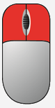
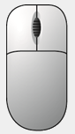
Working with the Mouse
|
When to Use |
How to Use |
Example |
|
|
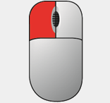
Select
|
Left Click |
|
|
|
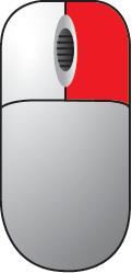
Options
|
Right Click |
|
|
|
Value Mode
|
Left and Right Click |
|
|
|
Left & Right Click Together |
Release Together |
||

Click n Go
Click n Go is a preference defined in Pattern Design that reduces the number of mouse clicks needed to complete a function. In most commands it is possible to edit multiple images, points, notches, lines, or pieces. For this reason there is a selection process of identifying the objects to change and then a confirmation step to confirm all necessary objects have been selected. This confirmation step is listed with “End Selection to Continue” in the prompt and then is completed by selecting the OK button in User Input or by right clicking and selecting OK. With Click n Go enabled the OK confirmation step is eliminated from the majority of PDS commands.
This reduction in mouse clicks allows commands to be completed quickly and efficiently while allowing edits to occur across multiple images, points, notches, lines, or pieces. All directions in this guide are written with the Click n Go feature enabled.
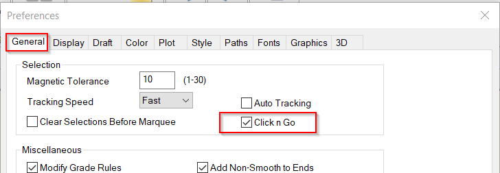
To Enable Click n Go in Pattern Design:
-
From the Edit tab, select the Customize dropdown and then Preferences in the Workspace panel.
-
Within the General tab, place a check mark in the Click n Go box in the Selection section.
-
Press Save to enable Click n Go permanently. Then press OK to exit.
Selecting Multiple Data Items with Click n Go
With Click n Go enabled, once an object such as a point, notch, line, or piece is selected the function will automatically move into the action. If multiple objects need to be selected there are three options available: random selection, grouping objects, and a combination.
To Select Multiple Data Items Using Random Selection:
-
When the prompt in the User Input states “Select”, press and hold the Ctrl key on the keyboard while using single left clicks to select all desired objects. The selected objects will change color as defined in the Preferences.
-
Once all desired objects have been selected release the Ctrl key. Releasing the Ctrl key will end the selection process and the function will be performed.
To Select Multiple Data Items Using Grouping Objects:
-
Draw a marquee box around the objects (pieces, lines and/or points) to select. Selection will end and/or function will be performed once the mouse button has been released.
To Select Multiple Data Items Using Combination:
-
Hold the Ctrl key down for marquee selection, multiple marquee selections, plus individual objects. Any combination of marquee and objects can be selected by holding down the Ctrl key. Use the SHIFT key to select a range. For example, in Create Trace select the first perimeter line, hold the Ctrl and Shift keys down and select the last line desired perimeter line in the clockwise direction. All lines in between are selected.
 Seams
Seams
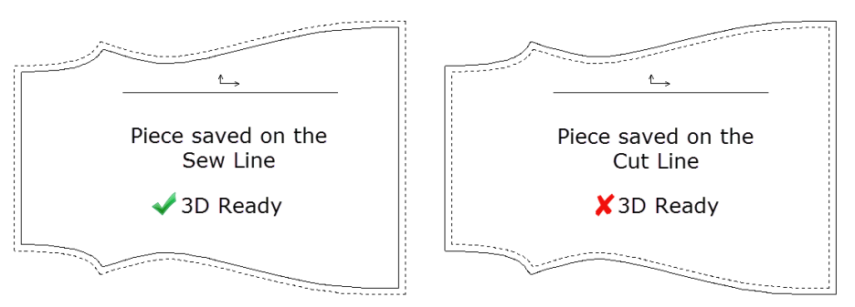
Stitching relationships in 3D preparation are defined on the sew lines of a pattern. This ensures the completed 3D virtualization is based on the finished garment measurements. For this reason, it is important that the garment is saved in the sew state prior to opening the model in the 3D workspace. The functions below discuss how to view, define, and swap seam allowance.
General seam allowance information includes:
-
A Cut Line is a line on a piece that will be used for cutting.
-
A Sew Line is a line on a piece where the pattern will be sewn when making the item. This is desired line for garment 3D preparation.
-
Pieces can be stored with either the sew or cut line as the piece perimeter/boundary. When a piece with the sew line as the perimeter is sent to marker making or to plot, the cut lines are automatically used. It is recommended that pieces are saved with the sew line as the piece perimeter.
-
Once seam allowance has been defined, the amount assigned to each line is saved as part of the piece information.
-
A warning message can be displayed when a selection is made on a non-perimeter (dashed) line. These selections will be ignored.
-
Sew or Cut displays in the Pattern Design Info bar when a piece is highlighted, indicating which line is currently the perimeter (solid) line.
-
Seams located in the Information bar can toggle the seam allowance display within the work area.
 Define
Use to add or remove seam allowances to one or more pieces, line-by-line or piece-by-piece. Uses a positive value to add cut lines or a negative value to add sew lines. Use a value of zero to remove seam allowance. For 3D preparation, this function is needed if no sew allowance is currently defined on the piece but built into the pattern.
To Add or Remove Seam Allowance:
-
From the Advanced tab, select Define in the Seam panel or press the Shift + F7 keys on the keyboard.
-
Select from the following User Input options:
-
Manual - Even – creates seam lines parallel to the existing line.
-
Manual - Uneven – defines seam line point-by-point for a tapered seam line.
-
Depending on what was chosen in the User Input options, the selection changes:
-
If Even was selected, select the lines that will receive the same amount of seam allowance. Use the Ctrl key to select multiple lines. Enter the amount of seam allowance in the User Input box.
-
If Uneven was selected, select the point(s) that will receive the same amount of seam allowance. Use the Ctrl key to select multiple points. Enter the seam allowance amount in the User Input box. Continue selecting points until the seam is defined for the whole line or piece.
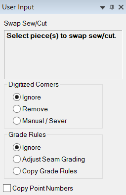
 Swap
Swap
Use to change the line that can be modified in Pattern Design. The solid line is the only line that can be modified. For 3D preparation, use this function if the solid line is the current outer perimeter of the piece (Cut Line). Once swapped, the piece will be in the Sew Line state and ready to create sewing relationships.
To Swap the Sew and Cut Lines:
-
From the Advanced tab, select Swap in the Seam panel or press the Shift + F8 keys on the keyboard.
-
Select from the following User Input options:
-
Ignore Digitized Corners – use when swapping a piece that has no digitized corners or for a piece that has computer-generated corners.
-
Remove Digitized Corners – eliminates digitized corner shapes when the piece is swapped. These corner lines are identified by defining 0 (zero) seam allowance on the corner line before swapping the seams.
-
Manual/Sever Digitized Corners – keeps digitized corner shapes when the piece is swapped. These corner lines are identified by defining 0 (zero) seam allowance on the corner line before swapping the seams.
-
Ignore Grade Rules – keeps the existing grading when the piece is swapped. This setting is used with the Generate Seam/Corners method in Seam Properties.
-
Adjust Seam Grading – modifies the grade rules to keep the seam lines parallel on all graded sizes. This setting can be used with Grade Seam/Corners method in Seam Properties.
-
Copy Grade Rules – places the grade rules from the perimeter on the system generated seam lines.
-
Copy Point Numbers – places the point number information from the perimeter on the system generated seam lines.
-
Select piece(s). Use the Ctrl key to select multiple pieces.