Model Editor
The Model Editor is the starting point in preparing AccuMark data for 3D simulation. Here you will be able to define fabric types, garment positions, body positions, layers and overlap types.
Model Editor: Basics
When preparing a garment for AccuMark 3D, it is necessary to group all required pieces in a model. This will identify the correct quantity and orientation for each piece. The fabric name will also be used to define fabric properties and images for the 3D simulation. The information below reviews the basic guidelines to create a model.
Creating the Model

A model is a list of all the pieces that make a finished item. You will be entering the following information in the Model Editor:
-
Number of pieces that will appear in a model
-
Number of pieces that will create opposites or “flips” on the X or Y axis
-
Fabric types each piece will be cut from
To Create a New Model:
-
Double click on the AccuMark Explorer icon located on the Desktop.
-
Locate and open the appropriate storage area, and then select all the pieces to include in the model. Use the Ctrl or Shift keys to select more than one piece. When finished selecting pieces, right click to select Open With ▸ Model Editor.
-
If desired, enter information in the Comments field. You can enter up to 40 characters per line.
-
Right clicking on the piece name and selecting Edit Piece Info can change the Category and Description columns. If this information is changed in the Model Editor, the piece will be updated as well.
Piece Categories are a powerful element of AccuMark piece naming and identification. AccuMark Pieces cannot be saved without a category. Each piece in an AccuMark Model must have a unique category (pieces with different fabric codes can have identical categories but this is not recommended). Piece Descriptions add yet another layer to piece naming and identification. Where Categories must be present for each piece, Descriptions are optional and can be duplicated among pieces in the model.
-
Enter a fabric code in the Fabric column. A fabric code is a user-defined code, up to ten characters in version 9 storage areas, that designates the material that a piece will be cut from in marker making and what fabric will be assigned to pieces. A fabric code must be assigned when using 3D. 3D uses the fabric characteristic details located in the fabric table to render garment simulation.
-
Type in the piece quantities in the Flips columns:
-
-- As digitized (as the piece appears in Pattern Design)
-
X Flipped over the x axis
-
Y Flipped over the y axis
-
X,Y Flipped over the x and y axes
-
-

-
From the File menu, select Save As. In the Save In box, select the storage area where the model will be saved. Enter the model name in the File Name box. When finished, click Save.
Note: Only one copy of a model should be open at one time. A model should not be opened and edited in the model editor and PDS at the same time.
Sample Video
This video demonstrates setting up a model.
Editing Existing Models
After a model is created, changes may be made by opening the existing model file. In AccuMark Explorer, select the storage area where the model is located. Double click the name of the model to open the Model Editor window.
Right Mouse Button Menu
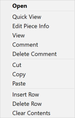
The following options are available by right-clicking on a piece name in the Model Editor:
-
Open – opens the piece into Pattern Design.
-
Quick View – displays the highlighted piece(s) in a single page.
-
Edit Piece Info – allows the piece category and description to be edited.
-
View – displays each piece in a separate window. Using this display, grade rules and notches are visible.
-
Comment – add a comment to the piece
-
Delete Comment – Delete a comment from the piece.
-
Cut – removes the highlighted information.
-
Copy – duplicates the highlighted information.
-
Paste – places the cut or copied information in the selected row.
-
Insert Row – adds an empty row above the highlighted row.
-
Delete Row – removes the highlighted row.
-
Clear Contents – removes the information from the highlighted row, but does not remove the row.
Fabric Information
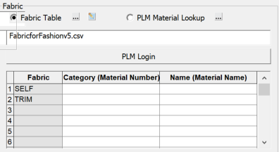
Next you must fill in the fabric information. The fabric information is important for 3D simulation to ensure the garments you are simulating have the proper stretch and drape properties. There are two options for specifying fabric information: Fabric Table or PLM Material.
-
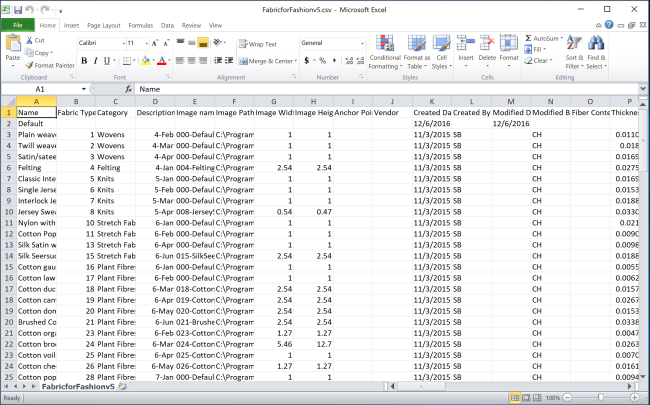
If a Fabric Table is selected, all of the fabrics along with the fabric properties are specified in a .csv file. There are a few tables included with the software you can edit these tables to add in your fabrics.
-
If PLM Material Lookup is selected, the fabric information is retrieved from a Yunique PLM database.
The Fabric Table contains details about the fabrics including the name, location, and dimensions of the fabric swatch. Once this information is saved with the model and the model is opened in PDS, the pieces will display with the fabric texture filled in the PDS work area. Make sure that the Preferences/Display/Filled Pieces and View/Filled Pieces and Trim view options are both ON.
Users can create their customized fabric table by collecting fabric properties and adding this to the fabric table. For detailed information, please go to the Fabric Properties and Testing for use with the AccuMark 3D at the end of this manual.
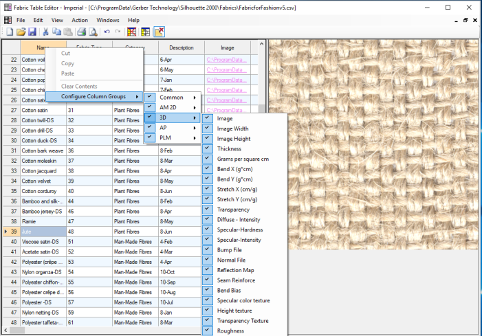
Fabric Table Configuration AccuMark Fabric tables can be used across the family of products including AccuMark Pattern Design, AccuPlan, AccuMark 3D and Yunique PLM. Users can configure fields based on the product they use. To configure fields, right-click in the title row, then select Configure Column Groups. Then select the product to display. Users can also activate and deactivate individual columns.
Fabric Types are copied to the Fabric section of the 3D Garment Info page.
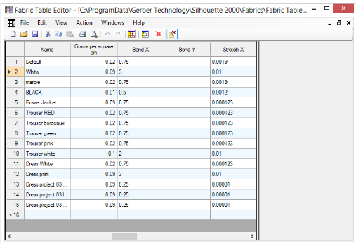
Fabric Table Editor
Fabric tables can be viewed in the Fabric Table Editor through the Model. The default path for the Fabric table is C:\ProgramData\Gerber Technology\Silhouette 2000\Fabrics.
Additional costing and inventory information can be added to the editor and referenced in additional AccuMark programs like AccuPlan. This allows for complete tracking from initial design to final production.
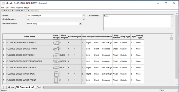
Model Editor: 3D Preparation Garment Information
In order to visualize garments in 3D, information needs to be provided about the model, pieces and fabric. The 3D Garment Info tab is where 3D information is added. This page includes garment and fabric information as well as additional piece properties necessary to wrap the patterns around the avatar.
After the first page of the Model is defined, the Pieces Names, Fabric Types and piece counts are copied to the 3D Garment Info page.
There are 3 main areas on the 3D Garment Info page:
-
Avatar
-
Garment Position
-
Piece Information
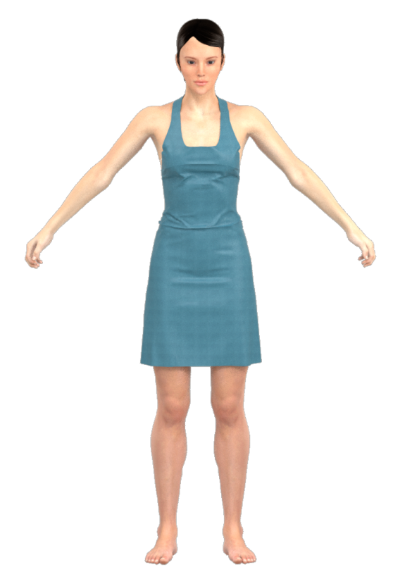
1. The Avatars
Users can either use the existing avatars or import their customized .obj file into the Avatar Editor and export them into .GtAvatar.
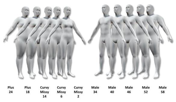
Standardized Avatars
The avatars provided with the system come in a variety of sizes and were generated using scanned data from the United States. The avatar’s name corresponds to the American Society for Testing and Materials (ASTM) size it resembles most. Most of the avatars are available in ‘A’ pose as well as 'Contra', standing ‘driving’ pose (arms forward), sitting driver, Sitting, and a casual standing pose. For more detailed information, see t Avatars can be measured using the Measure Tools in the Avatar Editor.
These avatars are located in C:\ProgramData\Gerber Technology\Silhouette 2000\Avatars with all supporting files. The standardized avatars have “Us” or "ASTM" prefix followed by the size, pose and file type. (Example: UsCurvyMissy14-APose.GtAvatar)
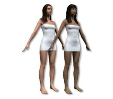
“Jane & Jennifer
Jane & Jennifer are two special avatars added to the AccuMark install. These avatars have shoulder length hair. The avatars hair is not a collision object and does not move. When simulating with these avatars, the garments will pass through the hair unobstructed. The avatars are available in ‘A’ pose only. They, like the standardized avatars, can be measured using the Avatar
Editor function.
These avatars are also located in C:\ProgramData\Gerber Technology\Silhouette 2000\Avatars with all supporting files. Jane & Jennifer are approximately a size 0 curvy by US standards.
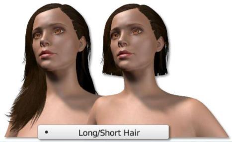
Jane & Jennifer also have the option to toggle their hair short or long. When running a cloth simulation with Jane.gtavatar or Jennifer.gtAvatar there will be a Long/Short Hair option in the right mouse button menu. Since their hair is a non-collision object, these avatars are not recommended for garments that cover the head.
2. Garment Position
The information in the Garment section identifies the general placement of the garment in relation to a specific avatar.
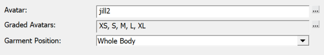
Garment Position – The Garment Position field specifies the location of the garment with regards of the body/avatar. This value helps arrange pieces in the 3D work area. The choices include Whole Body, Upper Body, Lower Body, Head, Feet, and Neck. Garment Position filters the options available in the Body Position drop-down list.
|
Position |
Garment Types |
|
|
Whole Body |
Dress, Jumpsuit, Swimsuit, Coveralls |
|
|
Upper Body |
Shirt, Bra, Jacket, Coat |
|
|
Lower Body |
Pants, Skirt, Panties |
|
|
Head |
Hat |
|
|
Feet |
Shoes |
|
|
Neck |
Scarf, Shawl |
3D Piece Information
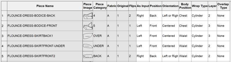
The pattern pieces’ names, fabric types, and piece counts are copied to the piece information section of the 3D Garment Info tab from the Model Editor tab. These items are “read only “and can only be modified in the Model Editor tab.
The Piece Information Table contains required information to assemble the garment in 3D. Here is where each pattern piece is assigned a location relative to the body/avatar.
Users will be allowed to edit this information to better arrange their pattern pieces depending on their design. This information can also be defined in PDS in the 3D menu using the Piece Properties function or Place Piece function.
-
As Input – The As Input specifies whether the original piece (prior to model specified flips) represents the left or right side of the garment.
This function defines the side of the piece. For mirrored piece, always check the direction of the folded piece to avoid flipped pieces in 3D working area.
-
Position – The Position field specifies the location of the pattern piece with regards to the body/avatar. The choices include Front, Back, Top, Side and Bottom.
-
Orientation – The Orientation specifies the location of the “As Input” and flipped pieces. The choices include None, Centered, Left and Right, Left Only and Right Only.
Usually, a piece that has flips (for example, a sleeve) on the opposite side of the body is “Left and Right”; a piece that locates on the center front or center back of the body (for example, collar, mirrored front and back pieces) is “Centered”; for other pieces, select “Left Only” or “Right Only” to define the piece, or select “None” to define it in 3D work area later or for pieces not included in the simulation.
-
Body Position – Each piece is positioned based on two reference locations: Piece position and Body Position. The options for Body Position vary depending on the current selection for Garment Position.
The following table shows the available 3D Body positions based on the Garment Position value.
|
Garment Position |
Body (3D) Positions |
|
Whole Body |
Shoulder Chest Neck Bicep Wrist Waist Hip Highest (point of foot) Tip of Toes Forehead Temple
|
|
Upper Body |
Shoulder Chest Neck Bicep Wrist Forehead Temple |
|
Lower Body |
Waist Hip Highest (point of foot) Tip of Toes |
|
Head |
Forehead Temple |
|
Feet |
Ankle Widest (part of the foot) Highest (point of foot) Arch Tip of Toes |
|
Neck |
Front (lowest center neck ) Back (highest center neck) |
-
Wrap Type – The Wrap Type specifies how the piece should be pre-shaped in the 3D view prior to draping. The default value is Cylinder. The options for this field include Flat and Cylinder. Cylinder should be used for all pieces that wraps around the body like a tube. The majority of pieces work well with cylinders.
-
Fabric Layer Position – The Fabric Layer Position specifies how the pieces should be layered relative to one another within a garment. A number is specified. The lower the number the closer the pattern will be to the body/avatar. For example a shirt front would be a 0 and the patch pocket on the shirt would be 1. The default is 1, if specifying layers be sure to change each piece as needed.
-
Fabric Overlap Type – The Fabric Overlap Type specifies how one piece lays on top of its flipped pair or to itself. The options include Left over right, Right over Left and None. For example a left front overlapping on the right front.